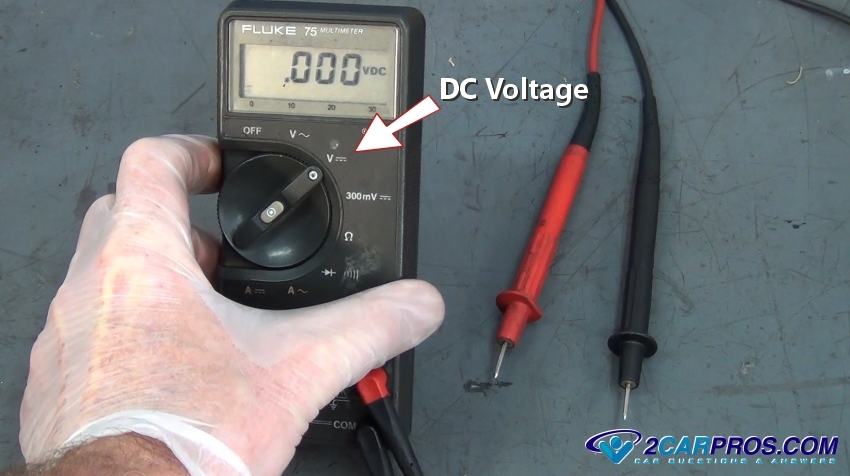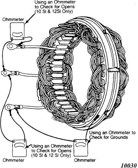
Diode Rectifier Alternator Download Scientific Diagram How to test alternator diode with multimeter voltmeter. super easyin this video we will show yo uhow to test alternator diode with multimeter and find out if. So, here is how to test the alternator by disconnecting the battery. first, pull the hand brake to secure the car and start the engine. after that, disconnect the negative battery terminal while the engine is running, and if it turns off, the alternator is faulty. the test itself is pretty straightforward.

тшс How To Test Alternator Diode Rectifier Step to check bridge rectifier diode. before checking. study this internal wiring of 4 diodes first. d1 and d3 arrow head has the same direction. d2 and d4 arrow head has the same direction too. How to use a rectifier diode. rectifier diodes allow current to flow in only one direction, from anode to cathode, also called forward bias. the rectifier diode in forward bias is made by connecting the anode to the most positive side and the cathode to the most negative side. you can see this in the example below:. In this article, we examined different faults of a diode bridge rectifier to provide some insight into troubleshooting an ac dc power supply. we saw that the frequency of the output ripples can be examined to verify if the diode bridge is functioning correctly or not. I want to design a precision rectifier with the circuit below by choosing proper r1, r2 and r3. i'm trying to analyze the question by considering vi>0 and vi<0. how can i know if d1 or d2 is conducting?.

тшс How To Test Alternator Diode Rectifier In this article, we examined different faults of a diode bridge rectifier to provide some insight into troubleshooting an ac dc power supply. we saw that the frequency of the output ripples can be examined to verify if the diode bridge is functioning correctly or not. I want to design a precision rectifier with the circuit below by choosing proper r1, r2 and r3. i'm trying to analyze the question by considering vi>0 and vi<0. how can i know if d1 or d2 is conducting?. 1. use the diode i v characteristic you measured in lab and the graphical method to find the voltage and current of the diode for the limiter and the half wave rectifier. compare these values with the values you obtained in preparation with different analysis methods and those obtained from lab measurement in steps 2 and 3. A half wave rectifier clips the negative half cycles and allows only the positive half cycles to flow through the load. thus it utilizes only the one half cycle of the input signal. during the positive half cycle (a positive & b negative) of the signal, the diode will be forward biased and conducts the current through the load resistance. A rectifier is a device that converts alternating current (ac) to direct current (dc), a process known as rectification. rectifiers are essentially of two types – a half wave rectifier and a full wave rectifier. In this hands on semiconductor electronics experiment, build a half wave rectifier circuit using a silicon diode and learn about the differences between permanent magnet motor operation on ac vs. dc power. in this project, you will build and test the half wave rectifying circuit, illustrated in figure 1. figure 1.

тшс How To Test Alternator Diode Rectifier 1. use the diode i v characteristic you measured in lab and the graphical method to find the voltage and current of the diode for the limiter and the half wave rectifier. compare these values with the values you obtained in preparation with different analysis methods and those obtained from lab measurement in steps 2 and 3. A half wave rectifier clips the negative half cycles and allows only the positive half cycles to flow through the load. thus it utilizes only the one half cycle of the input signal. during the positive half cycle (a positive & b negative) of the signal, the diode will be forward biased and conducts the current through the load resistance. A rectifier is a device that converts alternating current (ac) to direct current (dc), a process known as rectification. rectifiers are essentially of two types – a half wave rectifier and a full wave rectifier. In this hands on semiconductor electronics experiment, build a half wave rectifier circuit using a silicon diode and learn about the differences between permanent magnet motor operation on ac vs. dc power. in this project, you will build and test the half wave rectifying circuit, illustrated in figure 1. figure 1.

тшс How To Test Alternator Diode Rectifier A rectifier is a device that converts alternating current (ac) to direct current (dc), a process known as rectification. rectifiers are essentially of two types – a half wave rectifier and a full wave rectifier. In this hands on semiconductor electronics experiment, build a half wave rectifier circuit using a silicon diode and learn about the differences between permanent magnet motor operation on ac vs. dc power. in this project, you will build and test the half wave rectifying circuit, illustrated in figure 1. figure 1.
