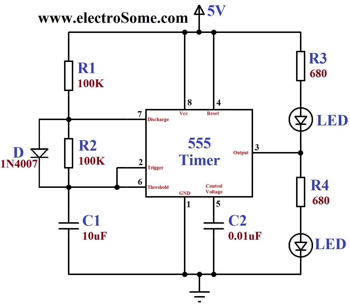
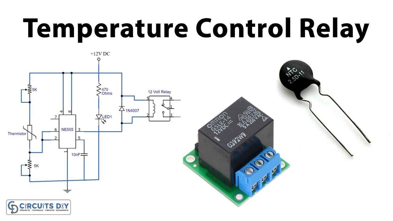
555 Timer Schematic 555 Timer Circuit Diagrams Different Modes Of Hot

555 Timer Schematic 555 Timer Circuit Diagrams Different Modes Of Hot All the electronics info you need to know about the 555 timer. with over 80 different electronic circuits that you can build. In this comprehensive guide, we’ll explore the 555 timer working principle, its block diagram, and circuit schematics. by the end, you’ll have a solid understanding of this amazing ic and be able to create your own projects with confidence.

Free Circuit Diagrams Timer 555 Schematic 555 timer ic provides time delay in circuits and here we discussed its pin diagram, various modes, working, circuits, and applications. This tutorial provides sample circuits to set up a 555 timer in monostable, astable, and bistable modes as well as an in depth discussion of how the 555 timer works and how to choose components to use with it. It has been used for many years because it is simple to understand, works in different ways, and fits many kinds of circuits. this article explains how the 555 timer works, what each pin does, and the different modes it can be used in. Clear and detailed diagram illustrating the configuration and connections for the 555 timer integrated circuit, helping with practical circuit assembly and troubleshooting.

Classic 555 Timer Chip Schematic Circuit It has been used for many years because it is simple to understand, works in different ways, and fits many kinds of circuits. this article explains how the 555 timer works, what each pin does, and the different modes it can be used in. Clear and detailed diagram illustrating the configuration and connections for the 555 timer integrated circuit, helping with practical circuit assembly and troubleshooting. Finally, we'll cover some of the most common applications of the 555 timer schematic diagram and its various modes of operation. at the heart of the 555 timer ic is a network of transistors and resistors connected together in a certain pattern, known as an astable multivibrator. In a typical circuit diagram below, this article presents one of the most sought after integrated circuits: the 555 timer ic. explaining several modes of operation such as the astable and monostable modes, it shows how the 555 timer ic can be used for timing, pulse generation and also oscillation. The 555 timer is a simple integrated circuit that can be used to make many different electronic circuits. with the following circuits analysis you will know how 555 ic works.

Schematic Of A 555 Timer Circuit Circuit Diagram Finally, we'll cover some of the most common applications of the 555 timer schematic diagram and its various modes of operation. at the heart of the 555 timer ic is a network of transistors and resistors connected together in a certain pattern, known as an astable multivibrator. In a typical circuit diagram below, this article presents one of the most sought after integrated circuits: the 555 timer ic. explaining several modes of operation such as the astable and monostable modes, it shows how the 555 timer ic can be used for timing, pulse generation and also oscillation. The 555 timer is a simple integrated circuit that can be used to make many different electronic circuits. with the following circuits analysis you will know how 555 ic works.

Adjustable Timer Circuit Using 555 50 Off Www Elevate In The 555 timer is a simple integrated circuit that can be used to make many different electronic circuits. with the following circuits analysis you will know how 555 ic works.
Comments are closed.