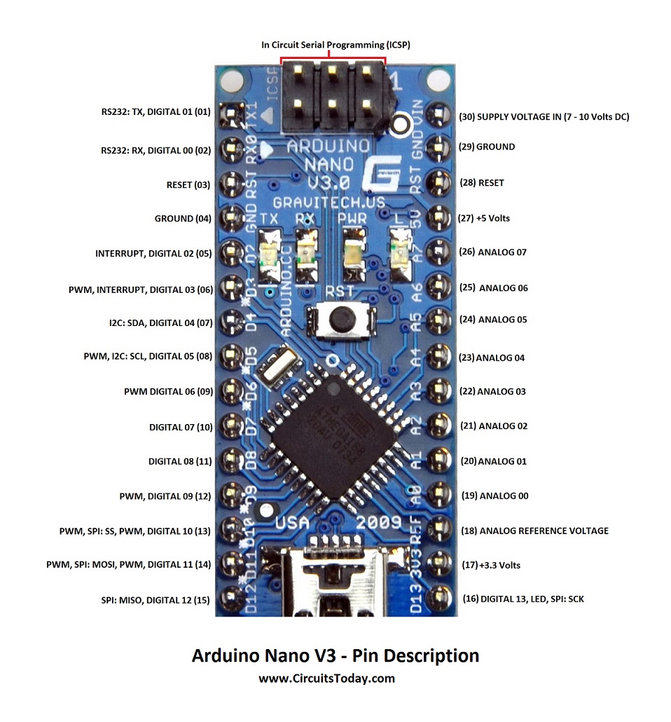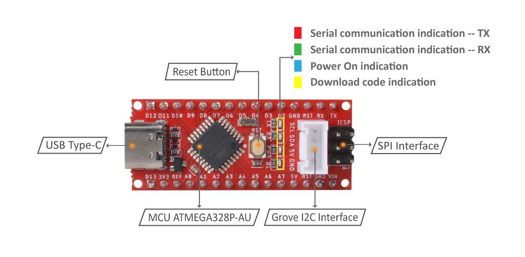
Arduino Nano Gpio Pinout Eroswag In this guide, learn about arduino nano pin outs and diagrams. we’ve created a well explained, diagram based pin out representation of arduino nano. arduino nano pinout. the arduino nano, as the name suggests is a compact, complete and bread board friendly microcontroller board. Learn how to switch between default & esp32 pin configurations when programming your board. the arduino nano esp32 is a nano form factor board based on an esp32 s3 soc. this board is part of the arduino nano family, and follows the same pinout as all nano boards.

Arduino Nano Gpio Pinout Eroswag It includes 14 digital i o pins (6 of which can be pwm outputs), 8 analog inputs, and an atmega328p microcontroller running at 16 mhz. pinout table. 14 digital input output pins with 6 pwm channels. 8 analog input pins. on board usb interface for easy programming and power. i2c and spi communication available for interfacing. The arduino nano every is a pin equivalent and evolved version of the arduino nano board. it comes with an even more powerful processor atmega4809 (20mhz), and a larger ram capacity of 6 kb (3 times). arduino nano every pinout is explained in detail in this post. Digital pins (d0 – d13): serve as input or output; operate at 0v or 5v. serial (rx, tx): for ttl serial data transmission and reception. external interrupts (2, 3): trigger interrupts. pwm (3, 5, 6, 9, 11): provide 8 bit pwm output. spi (10, 11, 12, 13): for spi communication. inbuilt led (13): controls an inbuilt led. To unlock its full potential, it’s crucial to understand the pin configuration of the arduino nano and how to use each pin effectively. in this blog, we’ll dive deep into the pin layout, functions, and applications of the arduino nano.

Arduino Nano Pinout Gpio Westpon Digital pins (d0 – d13): serve as input or output; operate at 0v or 5v. serial (rx, tx): for ttl serial data transmission and reception. external interrupts (2, 3): trigger interrupts. pwm (3, 5, 6, 9, 11): provide 8 bit pwm output. spi (10, 11, 12, 13): for spi communication. inbuilt led (13): controls an inbuilt led. To unlock its full potential, it’s crucial to understand the pin configuration of the arduino nano and how to use each pin effectively. in this blog, we’ll dive deep into the pin layout, functions, and applications of the arduino nano. This article will explore the arduino nano’s pinout, explaining each pin’s function and providing practical insights on how to effectively use them in your diy projects—whether you’re working with digital i o, analog inputs, power supply, or special functions. Are all the digital and analog gpio pins on the board directly (or thereabouts) connected to the atmega328p chip? i've checked the datasheet and i've researched for quite a few hours now. i know raspberry pi gpios are directly connected to the microprocessor chip but unable to find a clear answer for an arduino nano board. When working with the arduino nano development board, it is essential to have a solid understanding of the gpio (general purpose input output) pins and how they function. these pins serve as the interface between the arduino board and external devices, allowing for both input and output operations. Pinout configuration of arduino nano. the arduino nano comes with several pins for various functions, making it ideal for a wide range of applications. here’s a breakdown of the key pins: reset pin (rst): used to reset the microcontroller. analog pins (a0 to a7): used for reading analog signals ranging from 0v to 5v.

Arduino Nano Pinout Gpio Tiklozen This article will explore the arduino nano’s pinout, explaining each pin’s function and providing practical insights on how to effectively use them in your diy projects—whether you’re working with digital i o, analog inputs, power supply, or special functions. Are all the digital and analog gpio pins on the board directly (or thereabouts) connected to the atmega328p chip? i've checked the datasheet and i've researched for quite a few hours now. i know raspberry pi gpios are directly connected to the microprocessor chip but unable to find a clear answer for an arduino nano board. When working with the arduino nano development board, it is essential to have a solid understanding of the gpio (general purpose input output) pins and how they function. these pins serve as the interface between the arduino board and external devices, allowing for both input and output operations. Pinout configuration of arduino nano. the arduino nano comes with several pins for various functions, making it ideal for a wide range of applications. here’s a breakdown of the key pins: reset pin (rst): used to reset the microcontroller. analog pins (a0 to a7): used for reading analog signals ranging from 0v to 5v.

Arduino Nano Gpio Pinout Kwao When working with the arduino nano development board, it is essential to have a solid understanding of the gpio (general purpose input output) pins and how they function. these pins serve as the interface between the arduino board and external devices, allowing for both input and output operations. Pinout configuration of arduino nano. the arduino nano comes with several pins for various functions, making it ideal for a wide range of applications. here’s a breakdown of the key pins: reset pin (rst): used to reset the microcontroller. analog pins (a0 to a7): used for reading analog signals ranging from 0v to 5v.
