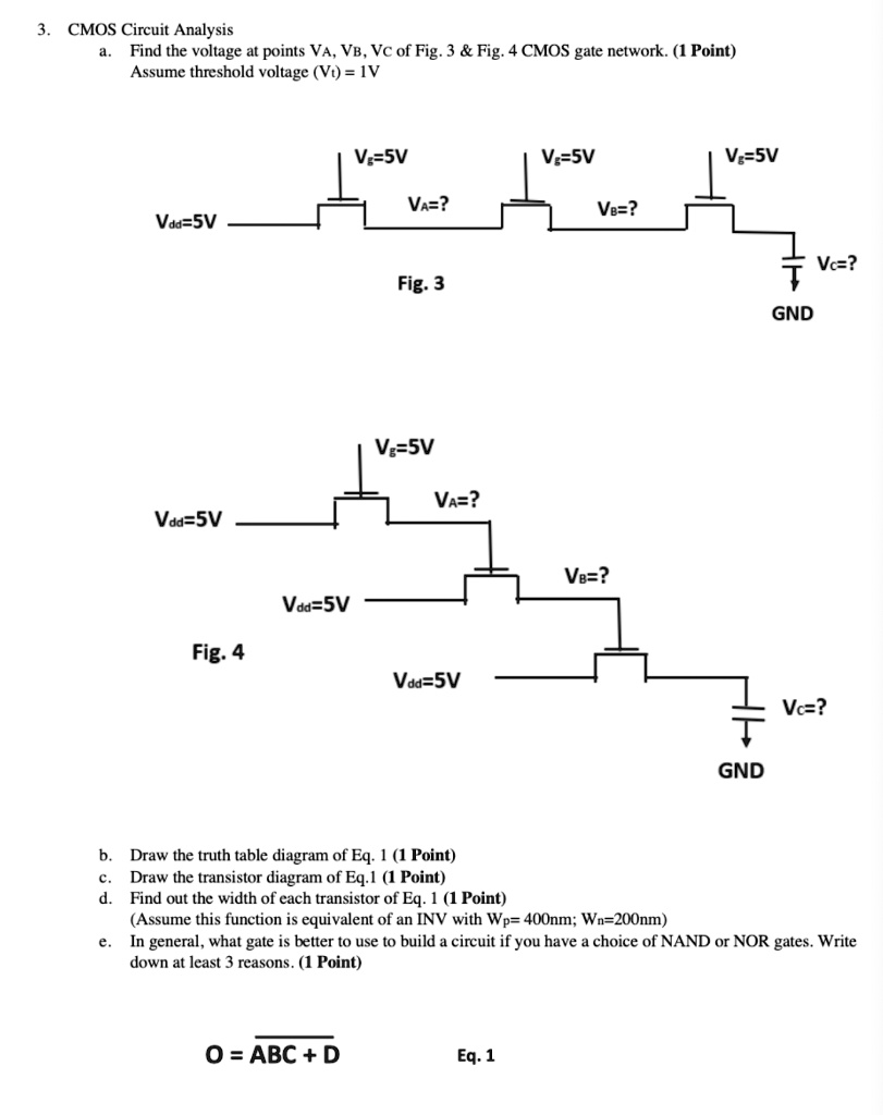
Solved 3 Cmos Circuit Analysis A Find The Voltage At Points Va Vb This paper presents a 2.5 v 5 v mixed voltage cmos i o buffer that does not need a cmos technology with a dual oxide option and complex bias circuits. the proposed mixed voltage i o buffer with simpler circuit structure can overcome the problems of leakage current and gate oxide reliability, which occurring in the conventional cmos i o buffer. This paper presents a 2.5 v 5 v mixed voltage cmos i o buffer that does not need a cmos technology with a dual oxide option and complex bias circuits.

Figure 6 From Design Of 2 5 V 5 V Mixed Voltage Cmos I O Buffer With In this paper, a new high voltage tolerant power rail esd clamp circuit, which combines the stacked nmos of low voltage devices with the substrate triggered technique, is designed to protect the mixed voltage i o interfaces against esd stresses. A 0.9 v to 5 v (0.9 1.2 1.8 2.5 3.5 5 v) mixed voltage i o buffer with nmos clamping technique is proposed. In this paper, the 2 v dd input tolerant mixed voltage i o buffer by using the nmos blocking technique has been verified in a 0.25 m 2.5 v cmos process to serve 2.5 5 v mixed voltage interface. The project submitted by krishna duvvada entitled “high speed digital cmos input buffer design” is hereby approved: dr. r. jacob baker, advisor date.

Figure 4 From Design Of 2 5 V 5 V Mixed Voltage Cmos I O Buffer With In this paper, the 2 v dd input tolerant mixed voltage i o buffer by using the nmos blocking technique has been verified in a 0.25 m 2.5 v cmos process to serve 2.5 5 v mixed voltage interface. The project submitted by krishna duvvada entitled “high speed digital cmos input buffer design” is hereby approved: dr. r. jacob baker, advisor date. The proposed mixed voltage i o buffer 1 has been implemented in a 0.25 m 2.5 v cmos process, which can be operated in the 2.5 5 v signal environment without the gate oxide reliability problem. the proposed mixed voltage i o buffer 2 can be applied for high speed applications without the gate oxide reliability problem and the circuit leakage issue. Abstract—a 0.9 v to 5.0 v (0.9 1.2 1.8 2.5 3.3 5 v) mixed voltage tolerant i o buffer carried out using cmos 2p4m 0.35 µm process is proposed in this paper. by using a dynamic gate bias generator to provide appropriate gate voltages for the output stage composed of stacked pmos and stacked nmos, the i o buffer. The new mixed voltage i o buffer has been fabricated and verified in a 0.25 μm cmos process to serve 2.5 5 v i o interface. besides, another 2.5 5 v mixed voltage i o buffer without the subthreshold leakage problem for high speed applications is also presented in this work. In this paper, a novel mixed voltage i o buffer without extra dual oxide cmos process is proposed. because it has the advantages of using the transmission gate (tg) as the dy namic switch and of a control circuit, this new mixed voltage i o buffer can avoid undesired damage caused by high volt ages.

Figure 1 From Design Of 2 5 V 5 V Mixed Voltage Cmos I O Buffer With The proposed mixed voltage i o buffer 1 has been implemented in a 0.25 m 2.5 v cmos process, which can be operated in the 2.5 5 v signal environment without the gate oxide reliability problem. the proposed mixed voltage i o buffer 2 can be applied for high speed applications without the gate oxide reliability problem and the circuit leakage issue. Abstract—a 0.9 v to 5.0 v (0.9 1.2 1.8 2.5 3.3 5 v) mixed voltage tolerant i o buffer carried out using cmos 2p4m 0.35 µm process is proposed in this paper. by using a dynamic gate bias generator to provide appropriate gate voltages for the output stage composed of stacked pmos and stacked nmos, the i o buffer. The new mixed voltage i o buffer has been fabricated and verified in a 0.25 μm cmos process to serve 2.5 5 v i o interface. besides, another 2.5 5 v mixed voltage i o buffer without the subthreshold leakage problem for high speed applications is also presented in this work. In this paper, a novel mixed voltage i o buffer without extra dual oxide cmos process is proposed. because it has the advantages of using the transmission gate (tg) as the dy namic switch and of a control circuit, this new mixed voltage i o buffer can avoid undesired damage caused by high volt ages.
