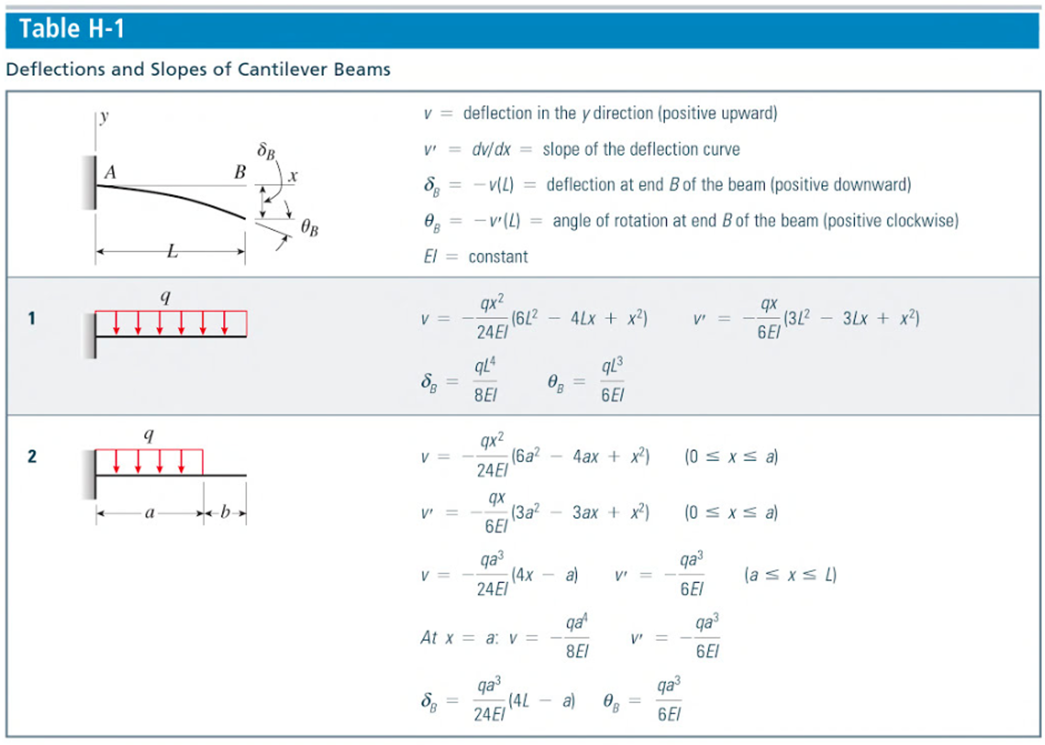
Load Steps Of A The Torsional Stiffness And B The Bending Stiffness Load steps of (a) the torsional stiffness and (b) the bending stiffness. in usual automobile practice, the structural optimization of a car body is based on changes in the topology, the. Superposition determines the effects of each load separately, then adds the results. separate parts are solved using any method for simple load cases. each effect is linearly related to the load that produces it. a load does not create a condition that affects the result of another load.

Load Steps Of A The Torsional Stiffness And B The Bending Stiffness When a beam is transversely loaded in such a manner that the resultant force passes through the longitudinal shear centre axis, the beam only bends and no torsion will occur. when the resultant acts away from the shear centre axis, then the beam will not only bend but also twist. (load) = (stiffness)(deformation) structural stiffness here is torsional stiffness = gj composed of two parts: g material contribution parameter j geometrical contribution parameter similar to bending: m = e x i d2w dx2 we can use the result in equations (13) and (14) to relate stress to torque: g dφ dx 1 = t j. Torsional stiffness is defined as the amount of torque required for twisting an object by unit radian. it is also known as the ratio of applied torque to the angle of twist (θ). it indicates how much the object is stiffer to withstand a torsional load. The torsional stiffness of the chassis frame can be calculated by finding the torque applied to the chassis frame and dividing by the angular deflection.

Bending Stiffness And Torsional Stiffness Values Of Branch 3 Of The B Torsional stiffness is defined as the amount of torque required for twisting an object by unit radian. it is also known as the ratio of applied torque to the angle of twist (θ). it indicates how much the object is stiffer to withstand a torsional load. The torsional stiffness of the chassis frame can be calculated by finding the torque applied to the chassis frame and dividing by the angular deflection. Real loading situations can be decomposed into the common modes of tension, compression, bending, and torsion. here we explore standard solutions to elastic problems, use them to derive material limits and indices, plot them onto material property charts, and finally review case studies. ii. bending of beams. iii. torsion of shafts. iv. The most critical load will occur if the person hangs from the bar with one hand. this is an obvious possibility and will cover the client’s spec #2. ranked in order from the most critical (students should show this!), the loading scenarios are: scenario 1: central concentrated load. maximum moment occurs if the entire load is. Vehicle skeleton is vital to confirm the load of varied elements and loads applied throughout vehicle operational area unit adequately supported while not vital deflection. the structure is likewise in charge of securing occupants and payloads amid crashes. Values for various shapes are given below (from materials selection in mechanical design, m.f. ashby). the shape factors are, from left to right, for: (1) elastic bending stiffness, (2) elastic torsional stiffness, (3) bending strength and (4) torsional strength.

Solved A Beam With Bending Stiffness E Iz Is Pinned At B And Chegg Real loading situations can be decomposed into the common modes of tension, compression, bending, and torsion. here we explore standard solutions to elastic problems, use them to derive material limits and indices, plot them onto material property charts, and finally review case studies. ii. bending of beams. iii. torsion of shafts. iv. The most critical load will occur if the person hangs from the bar with one hand. this is an obvious possibility and will cover the client’s spec #2. ranked in order from the most critical (students should show this!), the loading scenarios are: scenario 1: central concentrated load. maximum moment occurs if the entire load is. Vehicle skeleton is vital to confirm the load of varied elements and loads applied throughout vehicle operational area unit adequately supported while not vital deflection. the structure is likewise in charge of securing occupants and payloads amid crashes. Values for various shapes are given below (from materials selection in mechanical design, m.f. ashby). the shape factors are, from left to right, for: (1) elastic bending stiffness, (2) elastic torsional stiffness, (3) bending strength and (4) torsional strength.

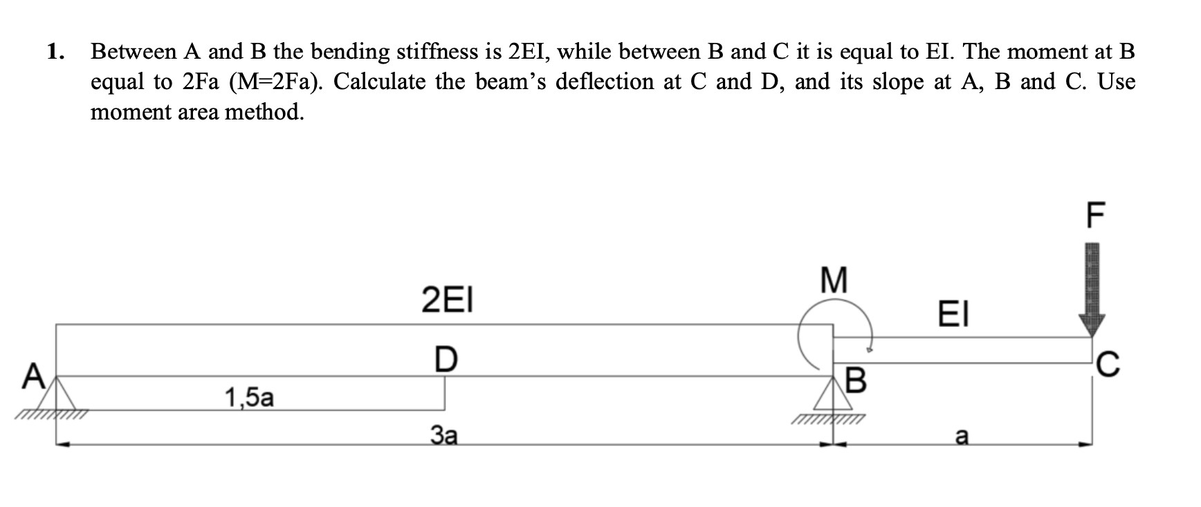
Solved Between A And B The Bending Stiffness Is 2ei While Chegg Vehicle skeleton is vital to confirm the load of varied elements and loads applied throughout vehicle operational area unit adequately supported while not vital deflection. the structure is likewise in charge of securing occupants and payloads amid crashes. Values for various shapes are given below (from materials selection in mechanical design, m.f. ashby). the shape factors are, from left to right, for: (1) elastic bending stiffness, (2) elastic torsional stiffness, (3) bending strength and (4) torsional strength.
