Solved Problem 19 52 Reference The Circuit Shown Below Chegg (assume €1 = 300 v and €2 = 170 v) (figure 1) calculate the current through the 40 12 resistor. (assume that the batteries have no internal resistance.) express your answer in amperes. Problem 19.52 reference the circuit shown below (assume e1 = 300 v and e2 = 170 v) (figure 1) calculate the current through the 40 Ω resistor (assume that the batteries.

Solved Consider The Circuit Shown In Figure 1 Assume E Chegg Video answer: in this problem, we have to find out, came through the 40 homeless sister in the circuit for part b. now we will use loop rule in luke, f. c. p g f. so we start from f and we will go in counter clockwise direction. Ver 2427 e1.1 analysis of circuits (2014) e1.1 circuit analysis problem sheet 1 solutions 1. circuit (a) is a parallel circuit: there are only two nodes and all four components are connected between them. circuit (b) is a series circuit: each node is connected to exactly two components and the same current must ow through each. 2. Example 2.1: consider the single loop circuit shown below. obtain the unknown current 𝑖. solution: kvl: 𝐕𝐚𝐛𝐕𝐛𝐜𝐕𝐜𝐝𝐕𝐝𝐚𝟎 ohm's law: 𝟖 e𝐢𝐛𝐜𝟒𝟎𝐢𝐝𝐚𝟒 l𝟎 ⇒𝟒𝐢 e𝟒𝐢𝟖 ⇒𝐢𝟏𝐦𝐀. Each problem presents a circuit diagram labeled with a figure number, states the unknown voltage(s) or current(s) to be solved for, and provides space for the written solution below. the document contains 19 circuit analysis problems involving the use of nodal analysis to solve for various voltages and currents.

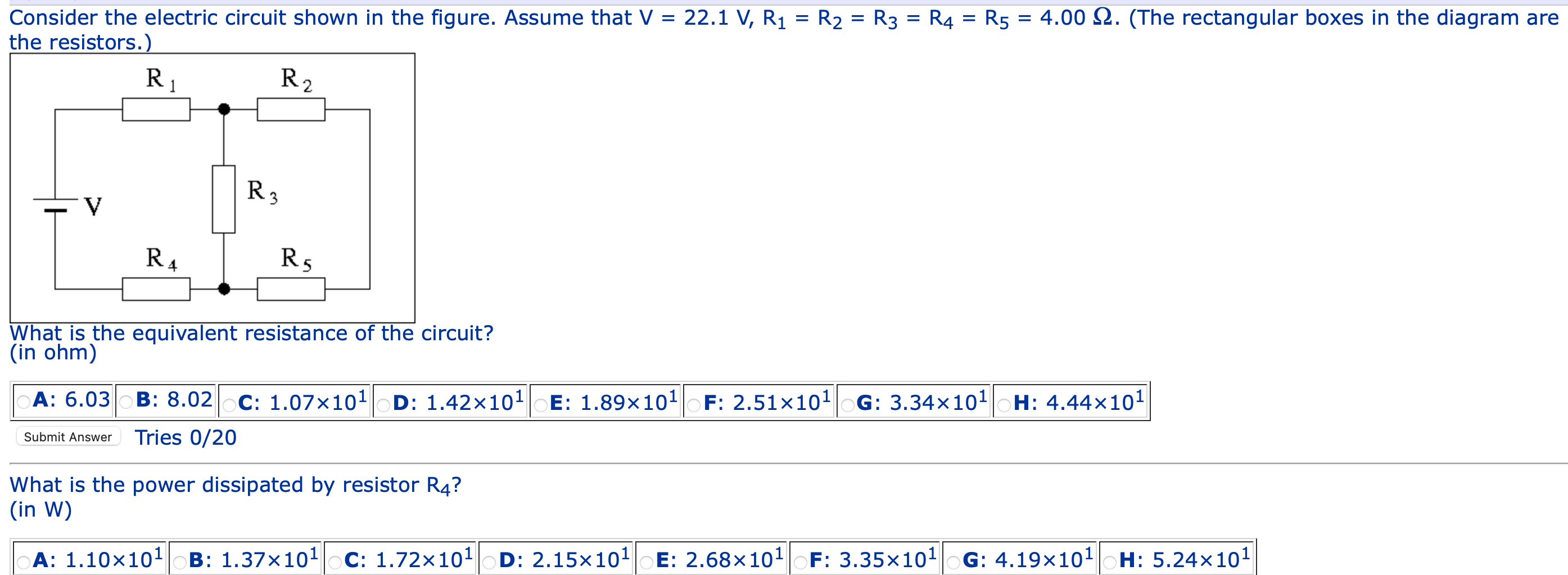
Solved Consider The Electric Circuit Shown In The Figure Chegg Example 2.1: consider the single loop circuit shown below. obtain the unknown current 𝑖. solution: kvl: 𝐕𝐚𝐛𝐕𝐛𝐜𝐕𝐜𝐝𝐕𝐝𝐚𝟎 ohm's law: 𝟖 e𝐢𝐛𝐜𝟒𝟎𝐢𝐝𝐚𝟒 l𝟎 ⇒𝟒𝐢 e𝟒𝐢𝟖 ⇒𝐢𝟏𝐦𝐀. Each problem presents a circuit diagram labeled with a figure number, states the unknown voltage(s) or current(s) to be solved for, and provides space for the written solution below. the document contains 19 circuit analysis problems involving the use of nodal analysis to solve for various voltages and currents. In complex circuits, you may be required to apply both of kirchhoff's laws. two 2 ohms resistors in parallel are equivalent to a 1 ohm resistor. now, voltage drop across each resistor can be find out using ohm's law. consider the circuit shown. match the resistor (s) to the voltage drop across them. Example iv–1. consider the circuit shown below, where r1 = 3.00 Ω, r2 = 10.0 Ω, r3 = 5.00 Ω, r4 = 4.00 Ω, and r5 = 3.00 Ω. (a) find the equivalent resistance of this circuit. (b) if the total power supplied to the circuit is 4.00 w, find the emf of the battery. − e r1 r2 r3 r4 r5 solution (a): we have to reduce this circuit in steps. Problem 1. (25 points) determine numerical value of input to output incremental voltage gain, a v = v out v in, for the circuit shown below. w l of m 1 is equal to w l = 500 1, all the pmos transistors have dimensions of w l = 1000 1, r l = 1k, and v b = 1:2v. you may ignore r ds. m 3 m 5 m 2 m 4 m 1 r l v out v b v in 5v ece342: electronic. Consider the circuit shown in figure (a). il(0 ) = 0, and vr(0 ) = 0. but, vr(0 ) vc(0 ) 10 = 0, or vc(0 ) = 10v. (a) at t = 0 , since the inductor current and capacitor voltage cannot change abruptly, the inductor current must still be equal to 0a, the capacitor has a voltage equal to –10v.

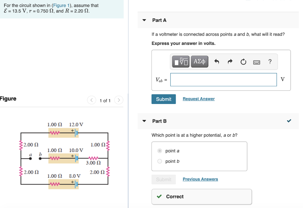
Solved For The Circuit Shown In Figure 1 Assume That E Chegg In complex circuits, you may be required to apply both of kirchhoff's laws. two 2 ohms resistors in parallel are equivalent to a 1 ohm resistor. now, voltage drop across each resistor can be find out using ohm's law. consider the circuit shown. match the resistor (s) to the voltage drop across them. Example iv–1. consider the circuit shown below, where r1 = 3.00 Ω, r2 = 10.0 Ω, r3 = 5.00 Ω, r4 = 4.00 Ω, and r5 = 3.00 Ω. (a) find the equivalent resistance of this circuit. (b) if the total power supplied to the circuit is 4.00 w, find the emf of the battery. − e r1 r2 r3 r4 r5 solution (a): we have to reduce this circuit in steps. Problem 1. (25 points) determine numerical value of input to output incremental voltage gain, a v = v out v in, for the circuit shown below. w l of m 1 is equal to w l = 500 1, all the pmos transistors have dimensions of w l = 1000 1, r l = 1k, and v b = 1:2v. you may ignore r ds. m 3 m 5 m 2 m 4 m 1 r l v out v b v in 5v ece342: electronic. Consider the circuit shown in figure (a). il(0 ) = 0, and vr(0 ) = 0. but, vr(0 ) vc(0 ) 10 = 0, or vc(0 ) = 10v. (a) at t = 0 , since the inductor current and capacitor voltage cannot change abruptly, the inductor current must still be equal to 0a, the capacitor has a voltage equal to –10v.
