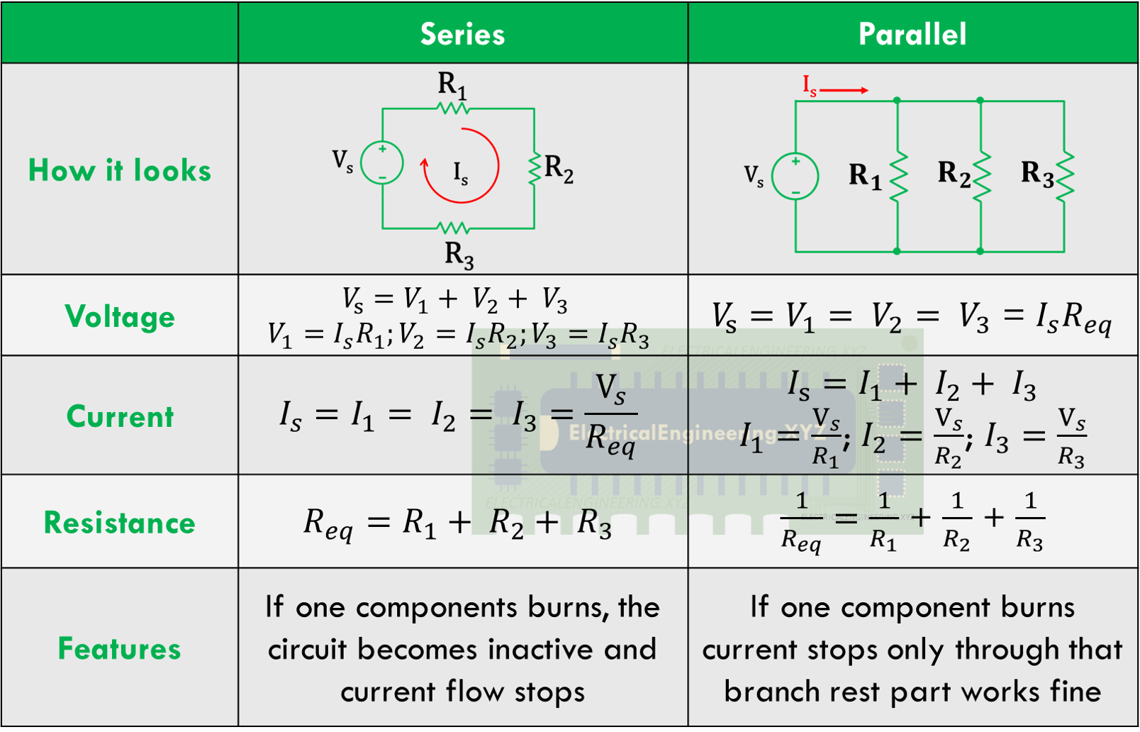
Series And Parallel Circuits Top Differences Circuit 48 Off What are top 5 differences between series and parallel circuits. a series circuit comprises of the head to head connection between two components. current always remains in such circuits while the voltage divides among series components. a parallel circuit configuration involves two or more components in which one end of all components share a. A series or a parallel circuit is determined by the arrangement of the circuit elements and the flow of current in that circuit. series circuit. if all the elements of a circuit are arranged in such a way that the magnitude of current that flows through each element is equal to the total current in the circuit, then the circuit is said to be a.

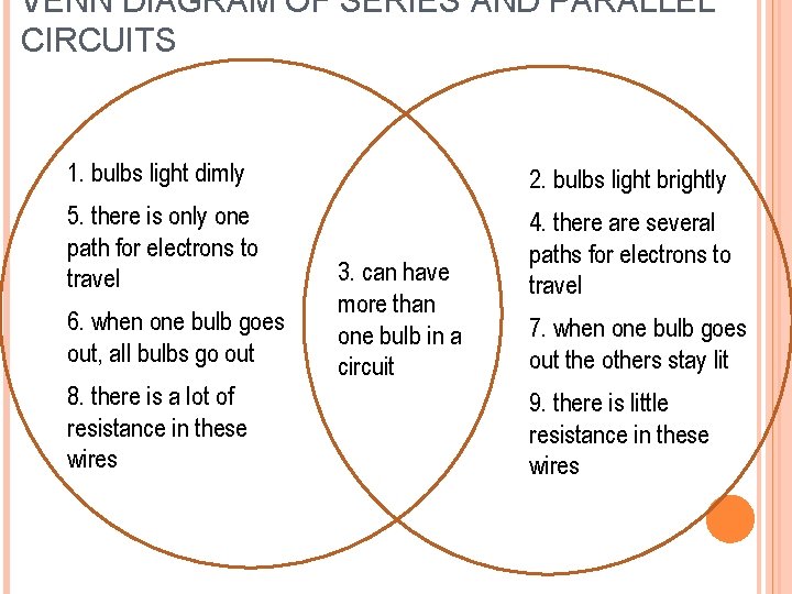
Series And Parallel Circuits Top Differences Circuit 48 Off Key differences between series and parallel circuits. in electrical and electronics engineering it is very important to know the differences between series and parallel circuits. they are the two most basic forms of electrical circuit and the other one being the series parallel circuit, which is the combination of both, can be understood by. Series vs parallel circuit review: in a series circuit, all components are connected end to end, forming a single path for current flow. in a parallel circuit, all components are connected across each other, forming exactly two sets of electrically common points. With electrical wiring, series and parallel circuits power multiple devices. they both have electrical current flowing through wires, but that's where the likeness ends. a series circuit is a closed circuit where the current follows one path. if one part of the circuit fails, the entire circuit fails. A series circuit diagram shows the components in a line, while a parallel circuit diagram shows the components side by side. by understanding the basics of series and parallel circuits, you can start to experiment and create different types of electrical systems.

Series And Parallel Circuits Top Differences Circuit 48 Off With electrical wiring, series and parallel circuits power multiple devices. they both have electrical current flowing through wires, but that's where the likeness ends. a series circuit is a closed circuit where the current follows one path. if one part of the circuit fails, the entire circuit fails. A series circuit diagram shows the components in a line, while a parallel circuit diagram shows the components side by side. by understanding the basics of series and parallel circuits, you can start to experiment and create different types of electrical systems. Series and parallel circuits with clear explanations, formulas, and examples. learn how to calculate resistance, current, and voltage in circuits. Much like the series circuit, the parallel circuit runs a current through more than one load. the difference is, the parallel circuit gives the current more than just one path to run around the circuit from start to finish. in a series circuit, one path is clearly defined while in parallel charges can move through different paths to find the end. This article explores the key differences between series and parallel circuits, their unique characteristics, and how they are applied in real world scenarios. whether you’re an aspiring electrical engineer, a hobbyist, or a curious learner, this guide will provide a comprehensive comparison of these two essential circuit types. Key differences between series and parallel circuits: series circuits have components connected in a single loop, which leads to a higher total resistance and the same current flowing through all components.

Differences Of Series And Parallel Circuits Circuit Diagram Series and parallel circuits with clear explanations, formulas, and examples. learn how to calculate resistance, current, and voltage in circuits. Much like the series circuit, the parallel circuit runs a current through more than one load. the difference is, the parallel circuit gives the current more than just one path to run around the circuit from start to finish. in a series circuit, one path is clearly defined while in parallel charges can move through different paths to find the end. This article explores the key differences between series and parallel circuits, their unique characteristics, and how they are applied in real world scenarios. whether you’re an aspiring electrical engineer, a hobbyist, or a curious learner, this guide will provide a comprehensive comparison of these two essential circuit types. Key differences between series and parallel circuits: series circuits have components connected in a single loop, which leads to a higher total resistance and the same current flowing through all components.

Series And Parallel Circuits Similarities Differences Circuit Diagram This article explores the key differences between series and parallel circuits, their unique characteristics, and how they are applied in real world scenarios. whether you’re an aspiring electrical engineer, a hobbyist, or a curious learner, this guide will provide a comprehensive comparison of these two essential circuit types. Key differences between series and parallel circuits: series circuits have components connected in a single loop, which leads to a higher total resistance and the same current flowing through all components.

Differences Of Series And Parallel Circuits Circuit Diagram
