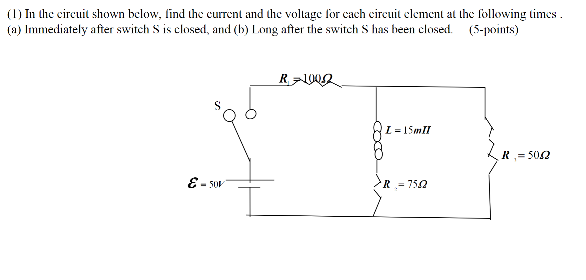
Solved Circuit Question 1 For The Circuit Shown A Find Chegg Draw the circuit in the phasor domain, using the impedances and the voltage phasor you have found. (5 marks) c) calculate the sinusoidal steady state voltages vi (t) and vr (t) shown in the figure using phasor analysis. (i.e. find the voltage phasors first, and then convert the phasors back into the time domain expressions v (t) and vr (t)) (10. If the voltage, current, charge and energy in a circuit are v, i, q and u respectively, then the correct relation is q4. if a pure inductor is connected across ac source, the average power taken by the inductor is .

Solved 1 In The Circuit Shown Below Find The Current And Chegg Example \(\pageindex{1}\) for the circuit show below find the current and voltage for each of the five resistors. solution. it is a good idea to start by labeling all the currents and voltage as shown below. since all the resistances are known, the first natural step is to find the equivalent resistance. Consider the circuit below with the mesh currents. but, we need one more equation, so we use the constraint equation –i3 i4 = 10. this now gives us three equations with three unknows. we can. Determine the currents in the relatively simple three wire circuit shown below. specify whether the current is flowing up or down the wire in each case. check out the circuit shown below. write kirchhoff's equations for this circuit. find the unknown currents i 1 and i 2. find the unknown battery voltage v 2. algebraic. To find the current through each resistor in a given circuit, one must use techniques such as series and parallel analysis, ohm's law, and kirchhoff's rules. the process includes calculating equivalent resistances, applying ohm's law to find the total current, and using a digital multimeter to measure current in a constructed circuit.

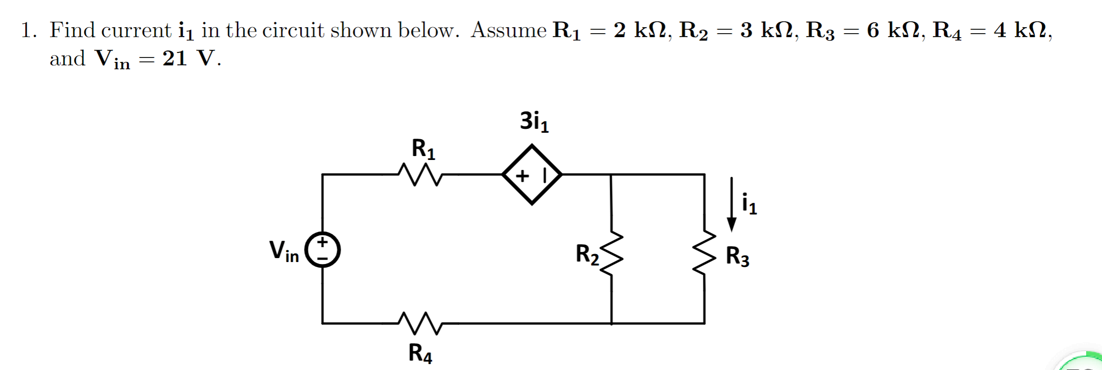
Solved 1 Find Current I1 In The Circuit Shown Below Assume Chegg Determine the currents in the relatively simple three wire circuit shown below. specify whether the current is flowing up or down the wire in each case. check out the circuit shown below. write kirchhoff's equations for this circuit. find the unknown currents i 1 and i 2. find the unknown battery voltage v 2. algebraic. To find the current through each resistor in a given circuit, one must use techniques such as series and parallel analysis, ohm's law, and kirchhoff's rules. the process includes calculating equivalent resistances, applying ohm's law to find the total current, and using a digital multimeter to measure current in a constructed circuit. In the circuit shown in figure (3.6), i is a dc current and v s is a sinusoidal signal. capacitor c is very large; its function is to couple the signal to the diode but block the dc current from flowing into the signal source. use the diode small signal model to show that the signal component of the output voltage is: v o = v s nv t nv t ir s. There are 2 steps to solve this one. the given circuits require us to calculate the modern day (i) inside the not the question you’re looking for? post any question and get expert help quickly. Consider the circuit shown in figure (a). i l(0 ) = 0, and v r(0 ) = 0. but, v r(0 ) v c(0 ) 10 = 0, or v c(0 ) = 10v. (a) at t = 0 , since the inductor current and capacitor voltage cannot change abruptly, the inductor current must still be equal to 0a, the capacitor has a voltage equal to –10v. since it is in series with the 10v. Find the values of current i and voltage v for the circuits shown below, assuming the diodes are ideal.(a)(b) your solution’s ready to go! our expert help has broken down your problem into an easy to learn solution you can count on.

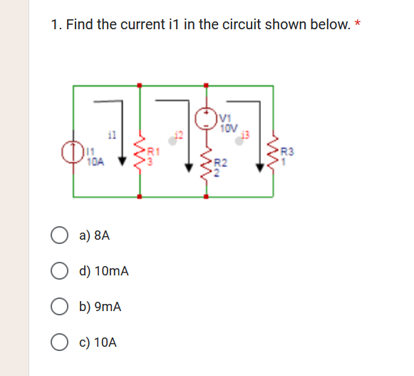
Solved 1 Find The Current I 1 In The Circuit Shown Below Chegg In the circuit shown in figure (3.6), i is a dc current and v s is a sinusoidal signal. capacitor c is very large; its function is to couple the signal to the diode but block the dc current from flowing into the signal source. use the diode small signal model to show that the signal component of the output voltage is: v o = v s nv t nv t ir s. There are 2 steps to solve this one. the given circuits require us to calculate the modern day (i) inside the not the question you’re looking for? post any question and get expert help quickly. Consider the circuit shown in figure (a). i l(0 ) = 0, and v r(0 ) = 0. but, v r(0 ) v c(0 ) 10 = 0, or v c(0 ) = 10v. (a) at t = 0 , since the inductor current and capacitor voltage cannot change abruptly, the inductor current must still be equal to 0a, the capacitor has a voltage equal to –10v. since it is in series with the 10v. Find the values of current i and voltage v for the circuits shown below, assuming the diodes are ideal.(a)(b) your solution’s ready to go! our expert help has broken down your problem into an easy to learn solution you can count on.

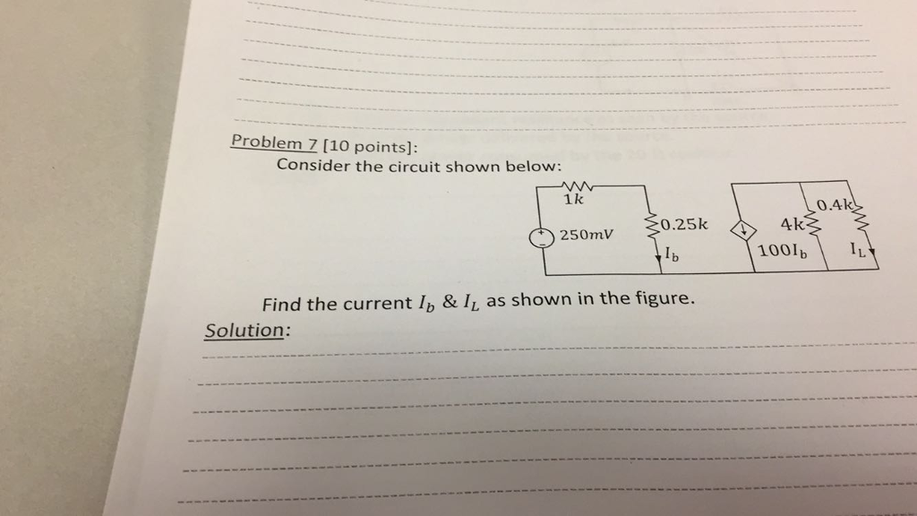
Solved Consider The Circuit Shown Below Find The Current Chegg Consider the circuit shown in figure (a). i l(0 ) = 0, and v r(0 ) = 0. but, v r(0 ) v c(0 ) 10 = 0, or v c(0 ) = 10v. (a) at t = 0 , since the inductor current and capacitor voltage cannot change abruptly, the inductor current must still be equal to 0a, the capacitor has a voltage equal to –10v. since it is in series with the 10v. Find the values of current i and voltage v for the circuits shown below, assuming the diodes are ideal.(a)(b) your solution’s ready to go! our expert help has broken down your problem into an easy to learn solution you can count on.
