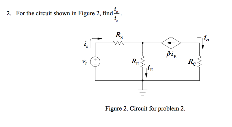
Solved 2 For The Circuit Shown In Figure 2 Find I0 Is Chegg B. (8 marks) for the circuit shown in figure 2 , i. (3 marks) calculate voltage and power in the independent current source. ii. (5 marks) calculate current i1. figure 2. your solution’s ready to go! our expert help has broken down your problem into an easy to learn solution you can count on. There are 2 steps to solve this one. the current i 1 in the circuit as shown in fig. has to be determined. not the question you’re looking for? post any question and get expert help quickly.

Solved 2 ï In The Circuit Shown In Figure 2 ï Find Chegg Q2. find the current through the diode in the circuit shown in fig. 2(i). assume the diode to be ideal. fig. 2. solution : we shall use thevenin’s theorem to find current in the diode. referring to fig. 2(i), fig. 2 (ii) shows thevenin’s equivalent circuit. since the diode is ideal, it has zero resistance. q3. If the interconnection in the figure is valid, find the total power developed in the circuit. if the interconnection is not valid, explain why. solution:. For the circuit shown in fig. 2 (i),find the maximum and minimum values of zener diode current. fig.2. solution : the first step is to determine the state of the zener diode. it is easy to see that for the given range of voltages (80 − 120 v), the voltage across the zener is greater than vz (= 50 v). 2.12 in the circuit shown in figure p2.12, find i1,i2,i3,i4,i5,i6, and i7. your solution’s ready to go! our expert help has broken down your problem into an easy to learn solution you can count on.

Solved 2 Consider The Circuit Shown In Figure 2 Below Chegg For the circuit shown in fig. 2 (i),find the maximum and minimum values of zener diode current. fig.2. solution : the first step is to determine the state of the zener diode. it is easy to see that for the given range of voltages (80 − 120 v), the voltage across the zener is greater than vz (= 50 v). 2.12 in the circuit shown in figure p2.12, find i1,i2,i3,i4,i5,i6, and i7. your solution’s ready to go! our expert help has broken down your problem into an easy to learn solution you can count on. The article provides an overview of nodal analysis, a method used in electrical circuit analysis that applies kirchhoff’s current law and source transformation techniques. it also includes a solved example to demonstrate how to apply nodal analysis to calculate currents in a simple circuit. 2.12 in the circuit in fig. 2.76, obtain v1, v2, and v3. law. design the problem by specifying values of ia, solve for values of i1, i2, and i3. be careful to specify. realistic currents. for prob. 2.12. branch currents i1 to i4. for prob. 2.8. 2.11 in the circuit of fig. 2.75, calculate v1 and v2. find i1, i2, and i3 in fig. 2.73. for prob. 2.13. For the circuit shown in figure (3.3), utilize the constant voltage drop model (0.7 v) for each conduction diode and show that the transfer characteristic can be described by: for 4.65 6 v. For the circuit in the figure below find vo(t) for t > 0. determine the time necessary for the capacitor voltage to decay to one third of its value at t = 0. problem 2. for the circuit below, find io for t > 0. problem 3. in the circuit below, find r, l, and τ. calculate the energy dissipated in the resistance for 0 < t < 0.5 ms. 4.

Solved 2 Find V2 In The Circuit Of Figure 2 Figure 2 Chegg The article provides an overview of nodal analysis, a method used in electrical circuit analysis that applies kirchhoff’s current law and source transformation techniques. it also includes a solved example to demonstrate how to apply nodal analysis to calculate currents in a simple circuit. 2.12 in the circuit in fig. 2.76, obtain v1, v2, and v3. law. design the problem by specifying values of ia, solve for values of i1, i2, and i3. be careful to specify. realistic currents. for prob. 2.12. branch currents i1 to i4. for prob. 2.8. 2.11 in the circuit of fig. 2.75, calculate v1 and v2. find i1, i2, and i3 in fig. 2.73. for prob. 2.13. For the circuit shown in figure (3.3), utilize the constant voltage drop model (0.7 v) for each conduction diode and show that the transfer characteristic can be described by: for 4.65 6 v. For the circuit in the figure below find vo(t) for t > 0. determine the time necessary for the capacitor voltage to decay to one third of its value at t = 0. problem 2. for the circuit below, find io for t > 0. problem 3. in the circuit below, find r, l, and τ. calculate the energy dissipated in the resistance for 0 < t < 0.5 ms. 4.

Solved Consider The Circuit Shown In Figure 2 Figure 2 Chegg For the circuit shown in figure (3.3), utilize the constant voltage drop model (0.7 v) for each conduction diode and show that the transfer characteristic can be described by: for 4.65 6 v. For the circuit in the figure below find vo(t) for t > 0. determine the time necessary for the capacitor voltage to decay to one third of its value at t = 0. problem 2. for the circuit below, find io for t > 0. problem 3. in the circuit below, find r, l, and τ. calculate the energy dissipated in the resistance for 0 < t < 0.5 ms. 4.

Solved 2 Find V2 In The Circuit Of Figure 2 Figure 2 Chegg
