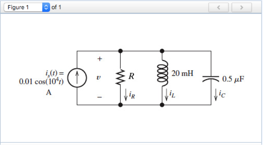
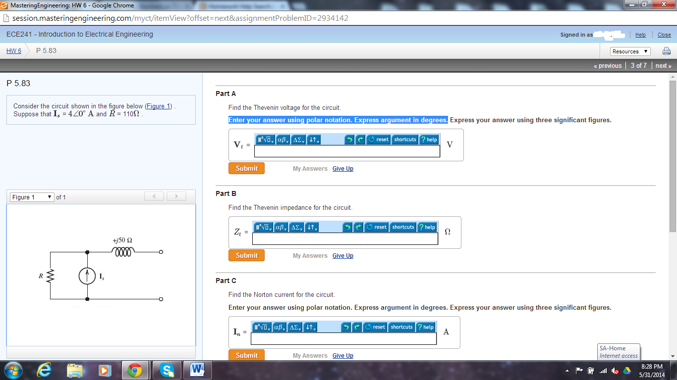
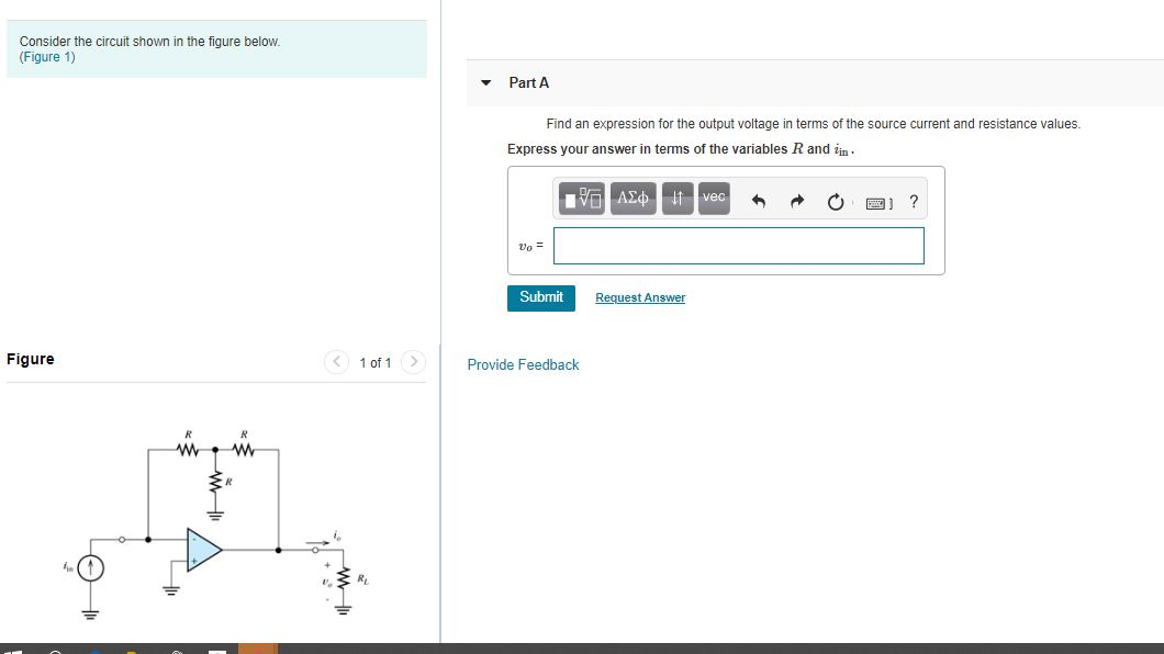
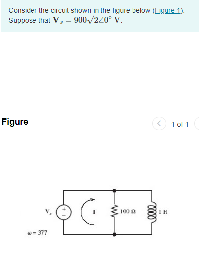
Solved Consider A Circuit Shown In The Figure Below Figure Chegg

Solved Consider The Circuit Shown In The Figure Below Vrogue Co Getting a covid 19 test buy self tests (at home tests) buy self tests (at home tests) online or in pharmacies and retail stores. if you have health insurance, it may reimburse the cost of purchasing self tests. visit fda's website for a list of authorized tests. go to a testing location visit a community based testing location, such as a pharmacy or health center near you. these locations may. This overview describes current information on the types of tests used to detect sars cov 2 infection and their intended uses. this information is intended for use by healthcare providers, public health professionals, and those organizing and implementing testing in non healthcare settings.

Solved Consider The Circuit Shown In The Figure Chegg Vrogue Co Laboratory testing can help distinguish whether someone is susceptible to ebv infection or has a recent or past infection. healthcare providers can test for antibodies to specific ebv associated antigens. monospot test is not recommended for general use. Laboratory diagnosis of lyme disease relies on serologic testing for antibodies to borrelia burgdorferi. cdc recommends a two step serologic testing process using fda cleared assays. serologic assays may be falsely negative during the first 4 6 weeks after infection. before cdc will recommend new tests, they must be cleared by the food and drug administration (fda). The ln34 pcr test for rabies is a newer diagnostic test that uses real time reverse transcriptase polymerase chain reaction (real time rt pcr) methodology to detect the presence of rabies virus genetic material. Laboratory testing cdc recommends the use of fda cleared antibody tests for laboratory diagnosis of lyme disease. as with antibody tests for other infectious diseases, the accuracy of these tests depends upon how long you've been infected. antibody tests may appear falsely negative during the first few weeks of infection, typically when a patient has an erythema migrans rash, but fda cleared.

Solved Consider A Circuit Shown In The Figure Below Figure Chegg The ln34 pcr test for rabies is a newer diagnostic test that uses real time reverse transcriptase polymerase chain reaction (real time rt pcr) methodology to detect the presence of rabies virus genetic material. Laboratory testing cdc recommends the use of fda cleared antibody tests for laboratory diagnosis of lyme disease. as with antibody tests for other infectious diseases, the accuracy of these tests depends upon how long you've been infected. antibody tests may appear falsely negative during the first few weeks of infection, typically when a patient has an erythema migrans rash, but fda cleared. This is a test (test) is a training and exercise simulation tool designed to foster collaborative emergency preparedness activities. it uses collaborative game theory and adult learning principles to increase engagement and knowledge retention. Waived test results, such as prothrombin time and glucose levels, adjust medication dosages for anticoagulant therapy and diabetes. in addition, erroneous results from diagnostic tests, such as those for human immunodeficiency virus (hiv) antibody, can have unintended consequences. Directions: patients wear their regular footwear and can use a walking aid, if needed. begin by having the patient sit back in a standard arm chair and identify a line 3 meters, or 10 feet away, on the floor. The enzyme linked immunosorbent assay is the most common serologic test for measuring antibody to cmv. congenital cmv infection cannot be diagnosed with antibody testing (igg and igm). the standard laboratory test for diagnosing congenital cmv infection is a pcr on saliva, with a confirmatory test on urine.

Solved Consider The Circuit Shown In The Figure Below Fi Chegg This is a test (test) is a training and exercise simulation tool designed to foster collaborative emergency preparedness activities. it uses collaborative game theory and adult learning principles to increase engagement and knowledge retention. Waived test results, such as prothrombin time and glucose levels, adjust medication dosages for anticoagulant therapy and diabetes. in addition, erroneous results from diagnostic tests, such as those for human immunodeficiency virus (hiv) antibody, can have unintended consequences. Directions: patients wear their regular footwear and can use a walking aid, if needed. begin by having the patient sit back in a standard arm chair and identify a line 3 meters, or 10 feet away, on the floor. The enzyme linked immunosorbent assay is the most common serologic test for measuring antibody to cmv. congenital cmv infection cannot be diagnosed with antibody testing (igg and igm). the standard laboratory test for diagnosing congenital cmv infection is a pcr on saliva, with a confirmatory test on urine.

Solved Consider The Circuit Shown In The Figure Below Chegg Directions: patients wear their regular footwear and can use a walking aid, if needed. begin by having the patient sit back in a standard arm chair and identify a line 3 meters, or 10 feet away, on the floor. The enzyme linked immunosorbent assay is the most common serologic test for measuring antibody to cmv. congenital cmv infection cannot be diagnosed with antibody testing (igg and igm). the standard laboratory test for diagnosing congenital cmv infection is a pcr on saliva, with a confirmatory test on urine.

Solved Consider The Circuit Shown In The Figure Below Chegg
Comments are closed.