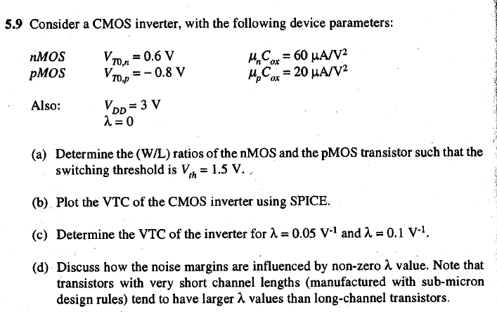
Solved Consider A Cmos Inverter With The Following Devic Chegg Determine the (w l) ratios of the nmos and the pmos transistor such that the switching threshold is vth = 0.6 v. b. plot the vtc of the cmos inverter using spice. Question: 6.8 consider a cmos inverter, with the following device parameters:nmos,vt0,n=0.8v,μncox=50μav2pmos,vt,p= 1.0v,μpcox=20μav2the power supply voltage is vdd=5v. both transistors have a channel length ofln=lp=1μm.

Solved 5 Consider A Cmos Inverter With The Following Device Chegg Determine the (wl) ratios of the nmos and the pmos transistor such that the switching threshold is vth=0.6v. plot the vtc of the cmos inverter using spice. determine the vtc of the inverter for ?=0.05v 1 and ?=0.1v 1. discuss how the noise margins are influenced by the nonzero ? value. Consider a cmos inverter, with the following device parameters: the power supply voltage is v dd = 5 v. both transistors have a channel length of l n = l p = 1 µm. the total output load capacitance of this circuit is c out = 2 pf, which is independent of transistor dimensions. Using the following device parameters for the transistors: and assuming the power supply voltage vdd is 3.3 v, find the (wn wp) ratio so that the switching (inversion) threshold voltage of the circuit is vm = 1.4v. how does the (wn wp) ratio differ from the ratio you found for the cmos inverter in homework #2, problem 3.1?. There are 3 steps to solve this one. the design of a cmos inverter centers around achieving a desired switching threshold voltage (vth) a not the question you’re looking for? post any question and get expert help quickly.

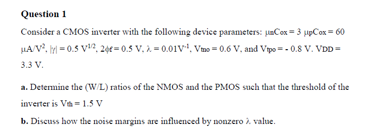
Solved Consider A Cmos Inverter With The Following Device Chegg Using the following device parameters for the transistors: and assuming the power supply voltage vdd is 3.3 v, find the (wn wp) ratio so that the switching (inversion) threshold voltage of the circuit is vm = 1.4v. how does the (wn wp) ratio differ from the ratio you found for the cmos inverter in homework #2, problem 3.1?. There are 3 steps to solve this one. the design of a cmos inverter centers around achieving a desired switching threshold voltage (vth) a not the question you’re looking for? post any question and get expert help quickly. Below is the detailed step by step solution: to satisfy the condition mentioned, the device needs to be in its specific operational state, which happens when the two sub components are equivalently conductive. this condition is denoted as idn = idp. This problem deals with a cmos inverter with the following parameters: vdd = 3v, vtn = 0.6v, vtp = 0.82v, k’n = 100μa v2, μn = 2.2μp. 1.3v. b) determine the relative device widths, wp wn, for vm = 1.3v. a cmos inverter with minimum sized transistors has βn =0.2ma v2, βp = 0.1ma v2 and vtn=|vtp|=0.6v.assume vdd = 3.3v. Consider a cmos inverter with the following device parameters: ncox = 3 pcox = 60 a v 2 , | = 0 v1 2, 2 f = 0 v, = 0 1, vtno = 0 v, and vtpo = 0 v. vdd = 3 v. a. determine the (w l) ratios of the nmos and the pmos such that the threshold of the inverter is vth = 1 v b. The given parameters are the threshold voltages for the nmos (vtn = 0.6 v) and pmos (vtp = 0.8 v), the supply voltage (vdd = 3 v), and the transconductance parameters for the nmos (coxn = 60 a v^2) and pmos (coxp = 20 a v^2).

Solved Consider A Cmos Inverter With The Following Device Chegg Below is the detailed step by step solution: to satisfy the condition mentioned, the device needs to be in its specific operational state, which happens when the two sub components are equivalently conductive. this condition is denoted as idn = idp. This problem deals with a cmos inverter with the following parameters: vdd = 3v, vtn = 0.6v, vtp = 0.82v, k’n = 100μa v2, μn = 2.2μp. 1.3v. b) determine the relative device widths, wp wn, for vm = 1.3v. a cmos inverter with minimum sized transistors has βn =0.2ma v2, βp = 0.1ma v2 and vtn=|vtp|=0.6v.assume vdd = 3.3v. Consider a cmos inverter with the following device parameters: ncox = 3 pcox = 60 a v 2 , | = 0 v1 2, 2 f = 0 v, = 0 1, vtno = 0 v, and vtpo = 0 v. vdd = 3 v. a. determine the (w l) ratios of the nmos and the pmos such that the threshold of the inverter is vth = 1 v b. The given parameters are the threshold voltages for the nmos (vtn = 0.6 v) and pmos (vtp = 0.8 v), the supply voltage (vdd = 3 v), and the transconductance parameters for the nmos (coxn = 60 a v^2) and pmos (coxp = 20 a v^2).
