Solved Consider The Circuit Shown In Figure 1 Part A Solve Chegg
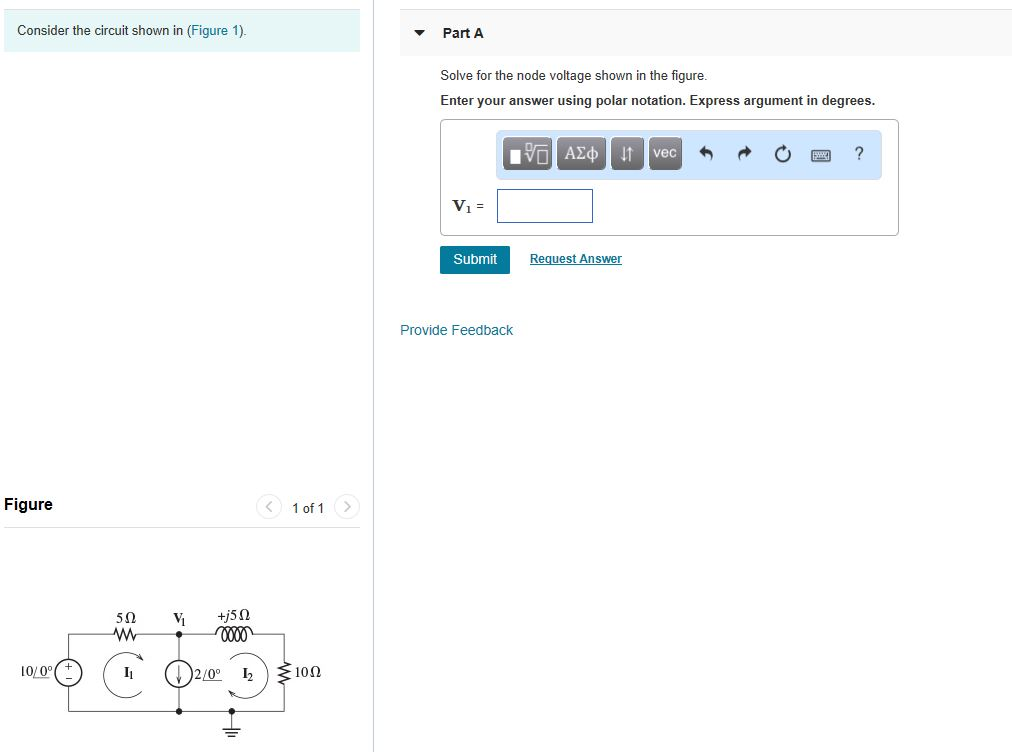
Solved Consider The Circuit Shown In Figure 1 Part A Solve Chegg The leading real estate marketplace. search millions of for sale and rental listings, compare zestimate® home values and connect with local professionals. Zillow has 133 homes for sale in mason city ia. view listing photos, review sales history, and use our detailed real estate filters to find the perfect place.
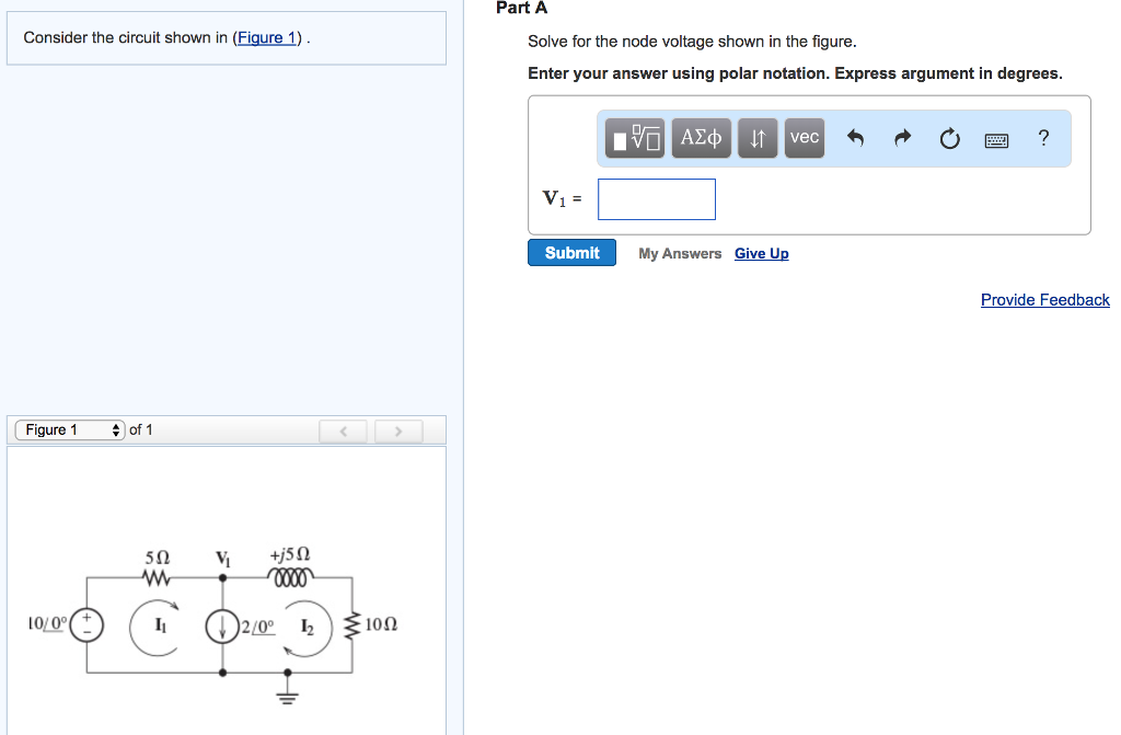
Solved Part A Consider The Circuit Shown In Figure 1 Solve Chegg Search new listings in mason city ia. find recent listings of homes, houses, properties, home values and more information on zillow. Search new listings in 50401. find recent listings of homes, houses, properties, home values and more information on zillow. Browse this list of states provinces to find all of the homes for which zillow has data. View 98 single family, condo townhouse, farm, land, multi family, commercial, rental, coop, mobile home properties for sale in mason city, ia. find pricing, photos and listing details, browse new listings and open houses, and find your next home.
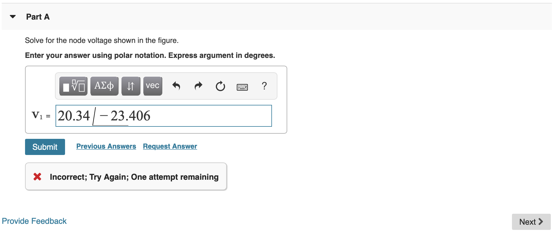
Solved Consider The Circuit Shown In Figure 1 Part A Solve Chegg Browse this list of states provinces to find all of the homes for which zillow has data. View 98 single family, condo townhouse, farm, land, multi family, commercial, rental, coop, mobile home properties for sale in mason city, ia. find pricing, photos and listing details, browse new listings and open houses, and find your next home. Main mason city multiple listing service | provided by greater mason city board of realtors. Zillow has 133 homes for sale in 50401. view listing photos, review sales history, and use our detailed real estate filters to find the perfect place. 89 single family homes for sale in mason city ia. view pictures of homes, review sales history, and use our detailed filters to find the perfect place. Mason city homes and properties for sale, real estate listings and apartments for rent by american realty.
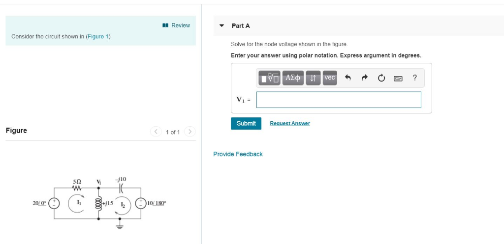
Solved Review Part A Consider The Circuit Shown In Figure Chegg Main mason city multiple listing service | provided by greater mason city board of realtors. Zillow has 133 homes for sale in 50401. view listing photos, review sales history, and use our detailed real estate filters to find the perfect place. 89 single family homes for sale in mason city ia. view pictures of homes, review sales history, and use our detailed filters to find the perfect place. Mason city homes and properties for sale, real estate listings and apartments for rent by american realty.
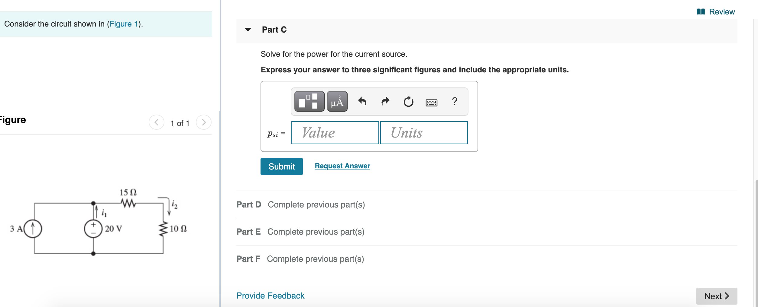
Solved 1 Review Consider The Circuit Shown In Figure 1 Chegg 89 single family homes for sale in mason city ia. view pictures of homes, review sales history, and use our detailed filters to find the perfect place. Mason city homes and properties for sale, real estate listings and apartments for rent by american realty.

Solved Consider The Circuit Shown In Figure 1 Solve For Chegg
Comments are closed.