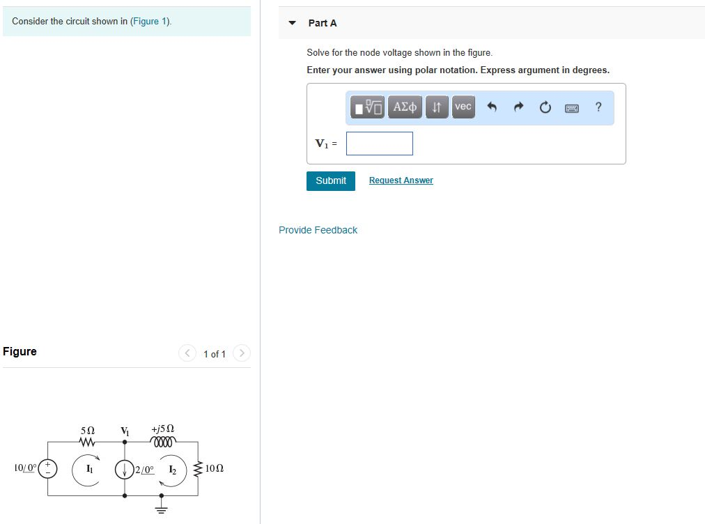
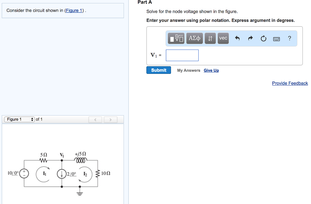
Solved Consider The Circuit Shown In Figure 1 Solve For Chegg

Solved 1 Consider The Circuit Shown In Figure 1 Below Chegg Consider the circuit shown in (figure 1). solve for the value of i1. express your answer to three significant figures and include the appropriate units. part b solve for the value of i2. express your answer to three significant figures and include the appropriate units. part c solve for the power for the current source. To approach this circuit problem, we first need to identify the values of the resistors and their configuration (series or parallel). given that the total voltage provided by the battery is e = 11v, we can analyze each part systematically.

Solved Consider The Circuit Shown In Figure 1 Part A Solve Chegg Consider the circuit shown in the figure below. [15 points] (a) obtain an expression for the apparent power, s, by the sending end voltage source, your answer should only contain vs, vr, δ, x, and b. [5 points] (b) obtain an expression for the real power generated by the sending end voltage source, vs. Instant answer step 1 4first, let's analyze the circuit and identify the components and their values. from the given information, we can see that there is a current source (i) with a value of 12 a, a resistor (r) with a value of 15 Ω, and another resistor (r2) with a value of 10 Ω. now, let's solve for the value of i. Part a consider the circuit shown in (figure 1). suppose that i, = 8a. find 21 . express your answer to three significant figures and include the appropriate units. 21 = value units submit request answer part b find v. express your answer to three significant figures and include the appropriate units. ? v = value show more show more. P 5.6 1 the circuit shown in figure p 5.6 1 consists of two parts separated by a pair of terminals. consider the part of the circuit to the left of the terminals.

Solved Part A Consider The Circuit Shown In Figure 1 Solve Chegg Part a consider the circuit shown in (figure 1). suppose that i, = 8a. find 21 . express your answer to three significant figures and include the appropriate units. 21 = value units submit request answer part b find v. express your answer to three significant figures and include the appropriate units. ? v = value show more show more. P 5.6 1 the circuit shown in figure p 5.6 1 consists of two parts separated by a pair of terminals. consider the part of the circuit to the left of the terminals. Consider a silicon sample maintained at 300k under equilibrium conditions, uniformly doped with 1*1016 cm 3 phosphorus atoms. the surface region of the sample is additionally doped uniformly with 5*1016 cm 3 boron atoms, to a depth of 1 microm, as shown in the figure below. Engineering electrical engineering electrical engineering questions and answers consider the circuit shown in (figure 1). suppose that vg= 75 v your solution’s ready to go! our expert help has broken down your problem into an easy to learn solution you can count on. see answer. Solve the previous question if the closed loop is completely enclosed in the circuit containing the switch. 1. an anticlockwise current pulse 2. a clockwise current pulse 3. an anticlockwise current pulse and then a clockwise current pulse 4. a clockwise current pulse and then an anticlockwise current pulse. previous question: consider the situation shown in figure. if the switch is closed and. Result page 50: step by step solutions for physics icse questions from expert tutors over 1:1 instant tutoring sessions. get solutions, concepts, examples or practice problems.
Comments are closed.