Consider The Circuit Shown In The Figure Below Assum Vrogue Co Our expert help has broken down your problem into an easy to learn solution you can count on. here’s the best way to solve it. not the question you’re looking for? post any question and get expert help quickly. (a) it can be used to calculate voltage, current and power. (b) it can be used to calculate voltage and current in a circuit containing resistor, capacitor, inductor and diode. (c) it can be used to calculate current in a circuit having linear elements resistor, capacitor and inductor.

Solved Consider The Circuit Shown In The Figure Below Vrogue Co If the voltage, current, charge and energy in a circuit are v, i, q and u respectively, then the correct relation is. Consider the circuit shown in the figure below (figure 1). suppose that is = 4∠0∘ a and r = 80 Ω . find the thevenin voltage for the circuit. find the thevenin impedance for the circuit. find the norton current for the circuit. find the maximum power that this circuit can deliver to a load if the load can have any complex impedance. Consider the circuit shown in figure (a). il(0 ) = 0, and vr(0 ) = 0. but, vr(0 ) vc(0 ) 10 = 0, or vc(0 ) = 10v. (a) at t = 0 , since the inductor current and capacitor voltage cannot change abruptly, the inductor current must still be equal to 0a, the capacitor has a voltage equal to –10v. Consider the circuit shown in the figure below. (let r1 = 7.00 Ω, r2 = 6.00 Ω, and e m f = 11.0 v.) (a) find the voltage across r1. v (b) find the current in r1. your solution’s ready to go! our expert help has broken down your problem into an easy to learn solution you can count on. question: consider the circuit shown in the figure below.

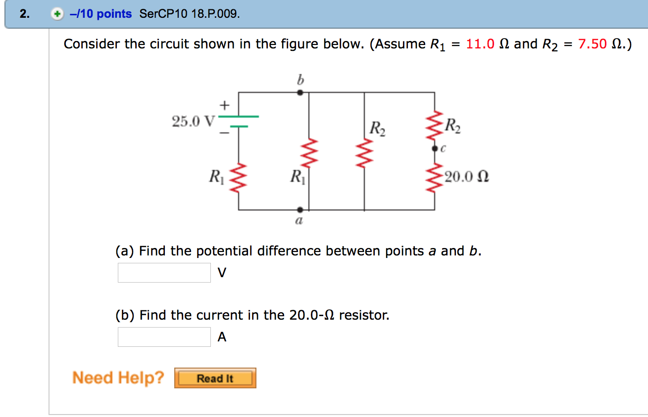
Consider The Circuit As Shown In Figure Below Consider the circuit shown in figure (a). il(0 ) = 0, and vr(0 ) = 0. but, vr(0 ) vc(0 ) 10 = 0, or vc(0 ) = 10v. (a) at t = 0 , since the inductor current and capacitor voltage cannot change abruptly, the inductor current must still be equal to 0a, the capacitor has a voltage equal to –10v. Consider the circuit shown in the figure below. (let r1 = 7.00 Ω, r2 = 6.00 Ω, and e m f = 11.0 v.) (a) find the voltage across r1. v (b) find the current in r1. your solution’s ready to go! our expert help has broken down your problem into an easy to learn solution you can count on. question: consider the circuit shown in the figure below. Figure p 3.2 3 (a) suppose that r 1 = 8 Ω and r 2 = 4 Ω. find the current i and the voltage v. so the circuit looks like the voltage across the 8 Ω resistor 𝒗 must be 12 volts since it is parallel with the 12 v source. therefore the current through the resistor 𝒊 can be found from ohm’s law. 𝒊 = 𝒗 𝑹 = 𝑽 𝛀. Consider the circuit shown in the figure below (figure 1). suppose that r1= 12 Ω, r2 = 26 Ω , r3 = 12 Ω , r4 = 34 Ω , r5 = 5 Ω and r6 = 6 Ω. a. determine the value of v2 by using mesh current analysis b. determine the power delivered by the source. If the voltage, current, charge and energy in a circuit are v, i, q and u respectively, then the correct relation is. The three branches recombine, the circuit extends to the left passing through point a, bends upward to a resistor labeled r1 and reaches the negative terminal of the battery. (a) find the potential difference between points a and b.

Solved Consider A Circuit Shown In The Figure Below Fig Figure p 3.2 3 (a) suppose that r 1 = 8 Ω and r 2 = 4 Ω. find the current i and the voltage v. so the circuit looks like the voltage across the 8 Ω resistor 𝒗 must be 12 volts since it is parallel with the 12 v source. therefore the current through the resistor 𝒊 can be found from ohm’s law. 𝒊 = 𝒗 𝑹 = 𝑽 𝛀. Consider the circuit shown in the figure below (figure 1). suppose that r1= 12 Ω, r2 = 26 Ω , r3 = 12 Ω , r4 = 34 Ω , r5 = 5 Ω and r6 = 6 Ω. a. determine the value of v2 by using mesh current analysis b. determine the power delivered by the source. If the voltage, current, charge and energy in a circuit are v, i, q and u respectively, then the correct relation is. The three branches recombine, the circuit extends to the left passing through point a, bends upward to a resistor labeled r1 and reaches the negative terminal of the battery. (a) find the potential difference between points a and b.

Solved Consider The Circuit Shown In Figure 1 Assume Vrogue Co If the voltage, current, charge and energy in a circuit are v, i, q and u respectively, then the correct relation is. The three branches recombine, the circuit extends to the left passing through point a, bends upward to a resistor labeled r1 and reaches the negative terminal of the battery. (a) find the potential difference between points a and b.

Solved Consider The Circuit Shown In The Figure Below
