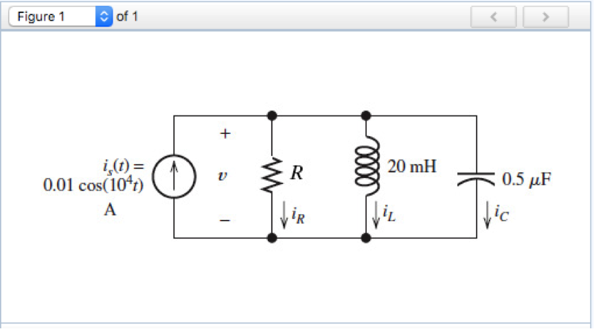
Solved Consider The Circuit Shown In The Figure Below Vrogue Co A rectangular circuit begins at the positive terminal of a battery labeled v, which is on the bottom side of the rectangle. the circuit extends up and to the left to resistor labeled r 2 on the top side of the rectangle. There are 2 steps to solve this one. 1. to find the eq not the question you’re looking for? post any question and get expert help quickly. answer to consider the circuit shown in the figure below. .

Solved Consider The Circuit Shown In The Figure Chegg Vrogue Co Study with quizlet and memorize flashcards containing terms like consider the circuit switched network shown in the figure below, with circuit switches a, b, c, and d. suppose there are 12 circuits between a and b, 20 circuits between b and c, 13 circuits between c and d, and 17 circuits between d and a., suppose that these maximum number of. Consider the circuit shown in the figure. whenever current has to be divided among resistors in parallel, use the current divider rule principle. Our expert help has broken down your problem into an easy to learn solution you can count on. question: consider the circuit shown in the figure below. (assume r=5.80Ω and Δv=16.0 v.) (a) find the equivalent resistance of the circuit in the figure. r. (b) find each current in the circuit. In an electric circuit, the maximum power transferred to load resistance is 2Ω is 50 w. if now, the load resistance is changed to 8Ω, what will be the power transferred to the load?.

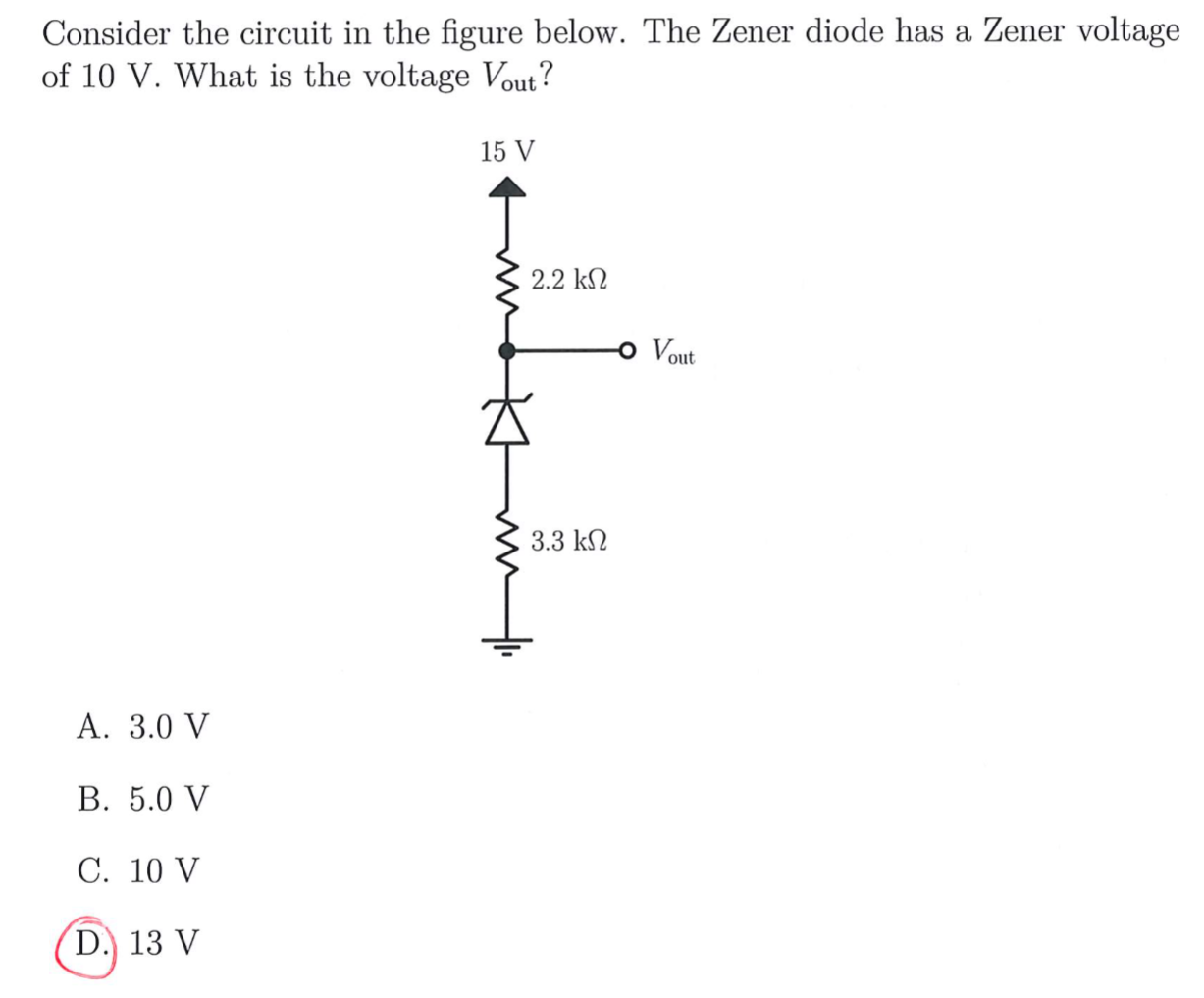
Solved 1 Consider The Circuit Shown In Below The Zene Vrogue Co Our expert help has broken down your problem into an easy to learn solution you can count on. question: consider the circuit shown in the figure below. (assume r=5.80Ω and Δv=16.0 v.) (a) find the equivalent resistance of the circuit in the figure. r. (b) find each current in the circuit. In an electric circuit, the maximum power transferred to load resistance is 2Ω is 50 w. if now, the load resistance is changed to 8Ω, what will be the power transferred to the load?. Consider the circuit shown in the figure. this law is also known as junction rule or current law (kcl). according to it the algebraic sum of currents meeting at a junction is zero i.e. Σ i = 0. Step by step solution to an electrical circuit problem using impedance and nodal analysis. ideal for electrical engineering students. Consider the circuit shown in figure (a). il(0 ) = 0, and vr(0 ) = 0. but, vr(0 ) vc(0 ) 10 = 0, or vc(0 ) = 10v. (a) at t = 0 , since the inductor current and capacitor voltage cannot change abruptly, the inductor current must still be equal to 0a, the capacitor has a voltage equal to –10v. Consider the circuit shown in the figure below (figure 1). suppose that r1= 12 Ω, r2 = 26 Ω , r3 = 12 Ω , r4 = 34 Ω , r5 = 5 Ω and r6 = 6 Ω a. determine the value of v2 by using mesh current analysis b. determine the power delivered by the source.

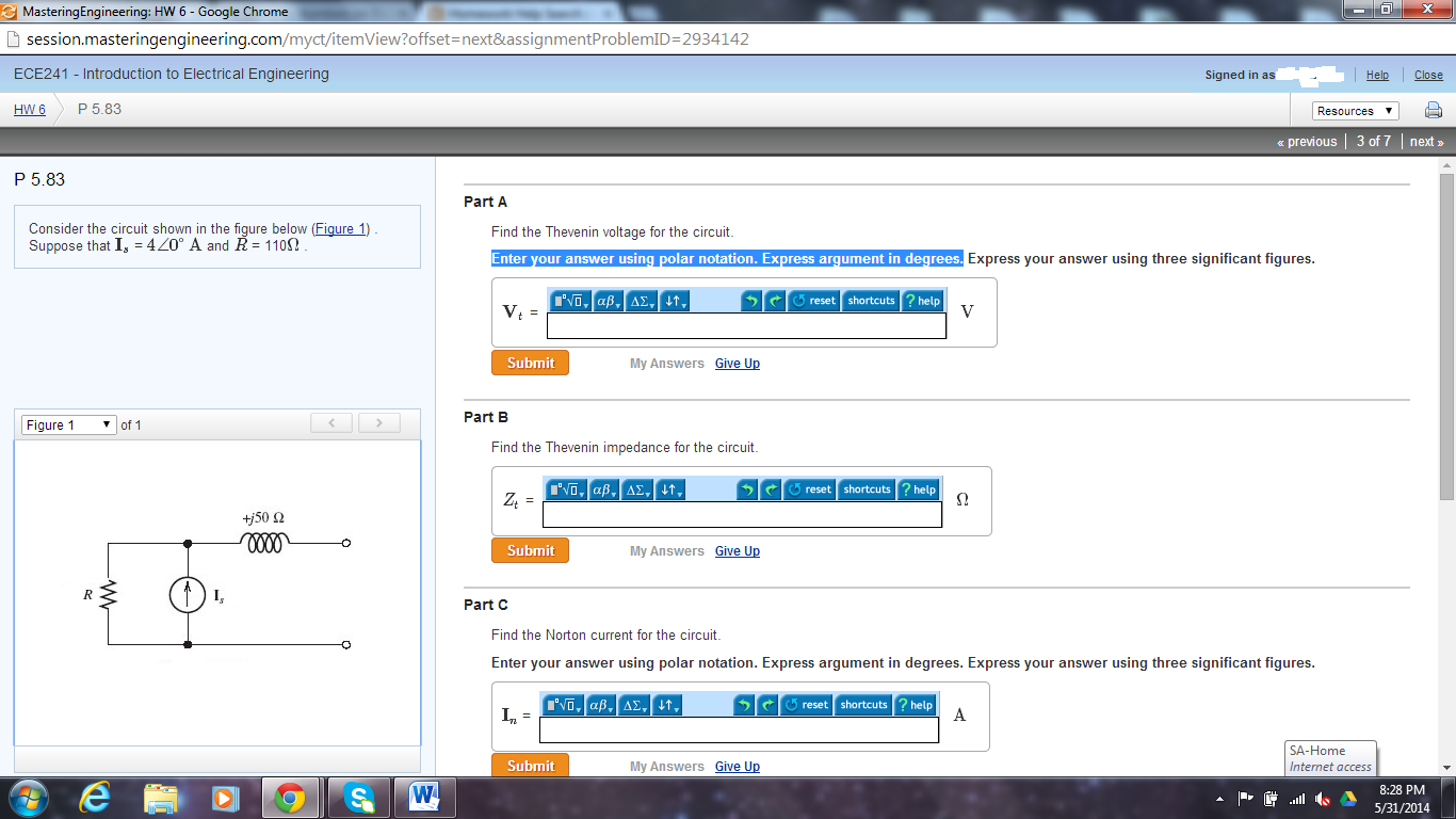
Solved Consider The Circuit Shown In Figure 1 Assume Vrogue Co Consider the circuit shown in the figure. this law is also known as junction rule or current law (kcl). according to it the algebraic sum of currents meeting at a junction is zero i.e. Σ i = 0. Step by step solution to an electrical circuit problem using impedance and nodal analysis. ideal for electrical engineering students. Consider the circuit shown in figure (a). il(0 ) = 0, and vr(0 ) = 0. but, vr(0 ) vc(0 ) 10 = 0, or vc(0 ) = 10v. (a) at t = 0 , since the inductor current and capacitor voltage cannot change abruptly, the inductor current must still be equal to 0a, the capacitor has a voltage equal to –10v. Consider the circuit shown in the figure below (figure 1). suppose that r1= 12 Ω, r2 = 26 Ω , r3 = 12 Ω , r4 = 34 Ω , r5 = 5 Ω and r6 = 6 Ω a. determine the value of v2 by using mesh current analysis b. determine the power delivered by the source.

Solved 2 Consider The Circuit Shown In Figure 2 Below Chegg Consider the circuit shown in figure (a). il(0 ) = 0, and vr(0 ) = 0. but, vr(0 ) vc(0 ) 10 = 0, or vc(0 ) = 10v. (a) at t = 0 , since the inductor current and capacitor voltage cannot change abruptly, the inductor current must still be equal to 0a, the capacitor has a voltage equal to –10v. Consider the circuit shown in the figure below (figure 1). suppose that r1= 12 Ω, r2 = 26 Ω , r3 = 12 Ω , r4 = 34 Ω , r5 = 5 Ω and r6 = 6 Ω a. determine the value of v2 by using mesh current analysis b. determine the power delivered by the source.

Solved Consider The Circuit Shown In The Figure Below Fi Chegg
