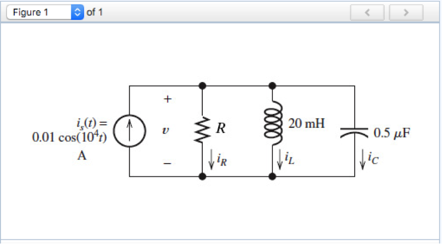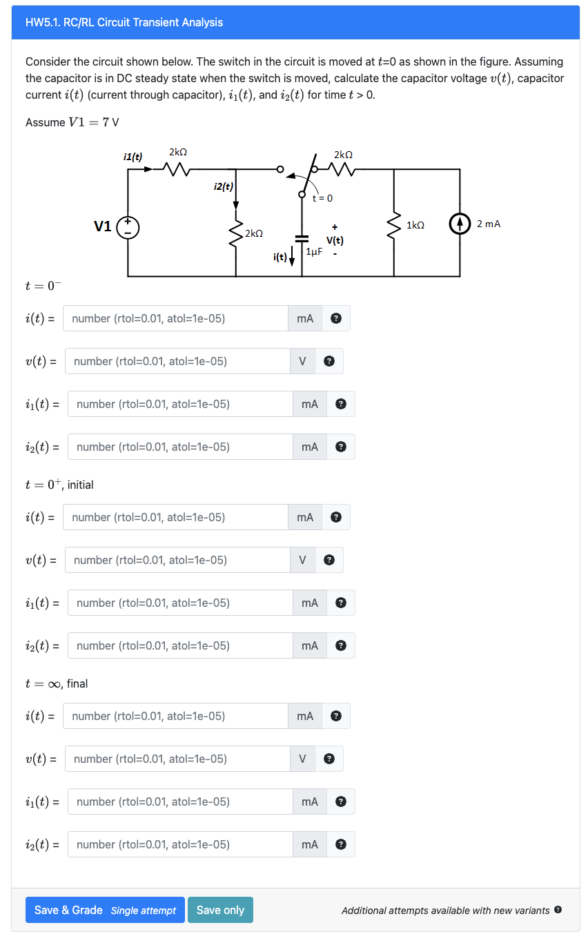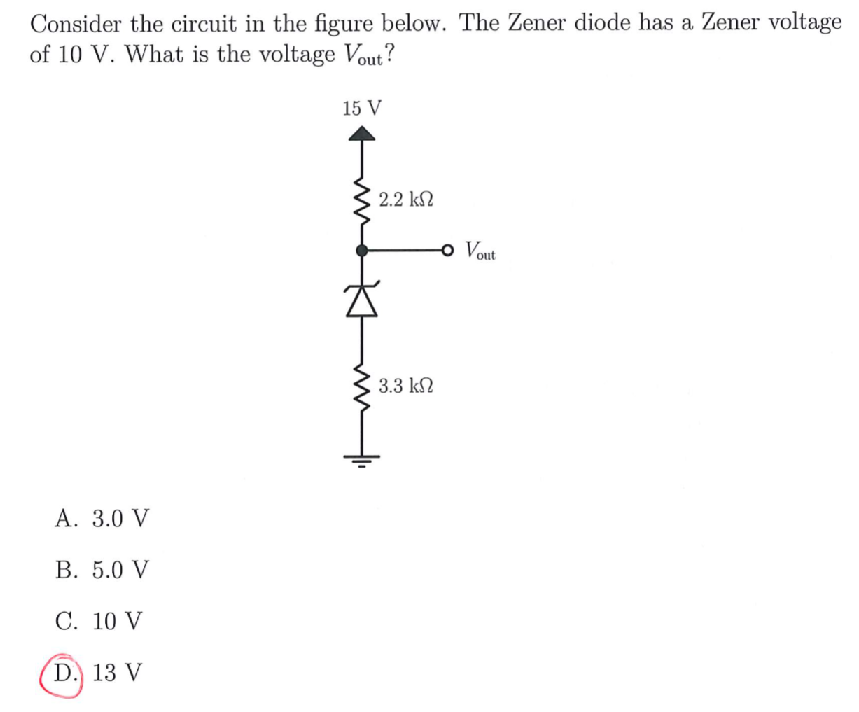
Solved Consider The Circuit Shown In The Figure Below Vrogue Co A rectangular circuit begins at the positive terminal of a battery labeled v, which is on the bottom side of the rectangle. the circuit extends up and to the left to resistor labeled r 2 on the top side of the rectangle. There are 2 steps to solve this one. 1. to find the eq not the question you’re looking for? post any question and get expert help quickly. answer to consider the circuit shown in the figure below. .

Solved Consider The Circuit Shown Below The Switch In The Chegg (a) it can be used to calculate voltage, current and power. (b) it can be used to calculate voltage and current in a circuit containing resistor, capacitor, inductor and diode. (c) it can be used to calculate current in a circuit having linear elements resistor, capacitor and inductor. Figure p 2.4 11 remember current sources provide the current specified and adjust their voltage accordingly. voltage sources provide the voltage specified and adjust their cur. Our expert help has broken down your problem into an easy to learn solution you can count on. question: consider the circuit shown in the figure below. (assume r=5.80Ω and Δv=16.0 v.) (a) find the equivalent resistance of the circuit in the figure. r. (b) find each current in the circuit. Consider the circuit shown in figure (a). il(0 ) = 0, and vr(0 ) = 0. but, vr(0 ) vc(0 ) 10 = 0, or vc(0 ) = 10v. (a) at t = 0 , since the inductor current and capacitor voltage cannot change abruptly, the inductor current must still be equal to 0a, the capacitor has a voltage equal to –10v.

Solved Consider The Circuit Shown In The Figure Chegg Vrogue Co Our expert help has broken down your problem into an easy to learn solution you can count on. question: consider the circuit shown in the figure below. (assume r=5.80Ω and Δv=16.0 v.) (a) find the equivalent resistance of the circuit in the figure. r. (b) find each current in the circuit. Consider the circuit shown in figure (a). il(0 ) = 0, and vr(0 ) = 0. but, vr(0 ) vc(0 ) 10 = 0, or vc(0 ) = 10v. (a) at t = 0 , since the inductor current and capacitor voltage cannot change abruptly, the inductor current must still be equal to 0a, the capacitor has a voltage equal to –10v. Consider the circuit shown in figure p 3.2 3. 3.2 3. 3.2 3. suppose that r1 = 8 Ω and r2. 4 Ω. find the current i and the voltage v. suppose, instead, that i = 2.25 a and . = 42 v. determine the resistances r1 and r2. suppose, instead, that the voltage source supplies 24 w of power and . ≥ an alternative way of solving this can be done by finding a thevenin equivalent circuit. first do a source transformation to simplify circuit and we get we can now identify the thevenin circuit as now we can do a voltage walk around the circuit and we get. Consider the circuit shown in the figure below (figure 1). suppose that r1= 12 Ω, r2 = 26 Ω , r3 = 12 Ω , r4 = 34 Ω , r5 = 5 Ω and r6 = 6 Ω a. determine the value of v2 by using mesh current analysis b. determine the power delivered by the source. Solution: consider the circuit below . use nodal analysis at nodes 1~4, now we can use matlab to solve for the unknown node voltage. calculate the node voltages v1, v2, and v3 in the.

Solved 1 Consider The Circuit Shown In Below The Zene Vrogue Co Consider the circuit shown in figure p 3.2 3. 3.2 3. 3.2 3. suppose that r1 = 8 Ω and r2. 4 Ω. find the current i and the voltage v. suppose, instead, that i = 2.25 a and . = 42 v. determine the resistances r1 and r2. suppose, instead, that the voltage source supplies 24 w of power and . ≥ an alternative way of solving this can be done by finding a thevenin equivalent circuit. first do a source transformation to simplify circuit and we get we can now identify the thevenin circuit as now we can do a voltage walk around the circuit and we get. Consider the circuit shown in the figure below (figure 1). suppose that r1= 12 Ω, r2 = 26 Ω , r3 = 12 Ω , r4 = 34 Ω , r5 = 5 Ω and r6 = 6 Ω a. determine the value of v2 by using mesh current analysis b. determine the power delivered by the source. Solution: consider the circuit below . use nodal analysis at nodes 1~4, now we can use matlab to solve for the unknown node voltage. calculate the node voltages v1, v2, and v3 in the.

Solved Consider The Circuit Shown In Figure 1 Assume Vrogue Co Consider the circuit shown in the figure below (figure 1). suppose that r1= 12 Ω, r2 = 26 Ω , r3 = 12 Ω , r4 = 34 Ω , r5 = 5 Ω and r6 = 6 Ω a. determine the value of v2 by using mesh current analysis b. determine the power delivered by the source. Solution: consider the circuit below . use nodal analysis at nodes 1~4, now we can use matlab to solve for the unknown node voltage. calculate the node voltages v1, v2, and v3 in the.
