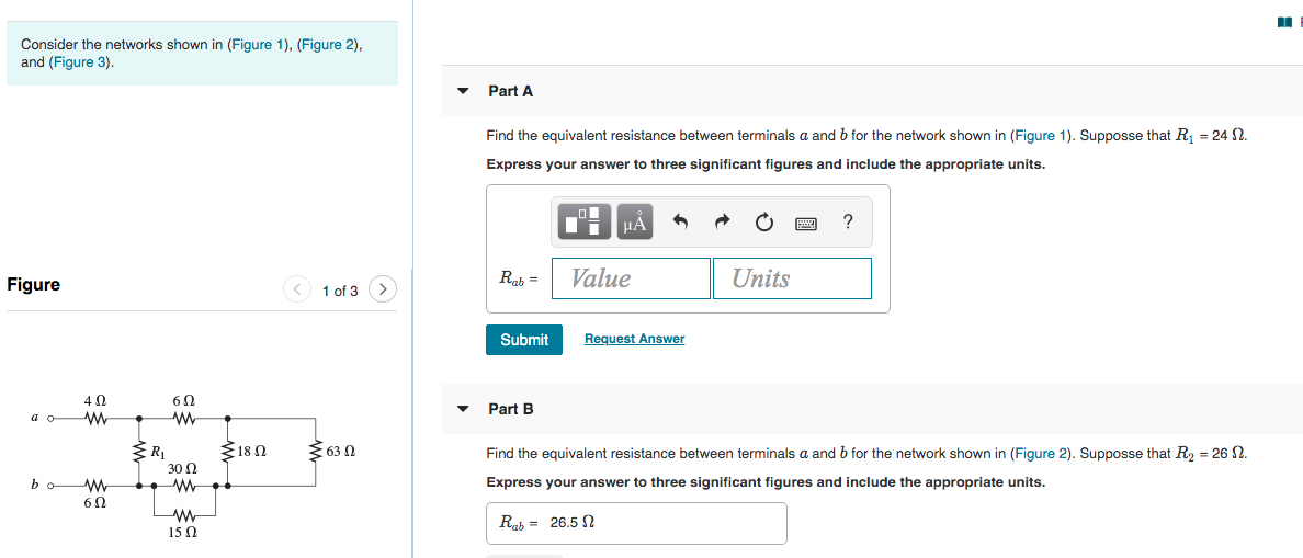
Solved Consider The Networks Shown In Figure 1 Figure Vrogue Co There are 3 steps to solve this one. this ai generated tip is based on chegg's full solution. sign up to see more! identify which resistors are in parallel in the given circuit configuration. here 63 Ω and 18 Ω are connected in parallel and also 30 Ω and 15 Ω are connected in parallel. then the combination will. Please use dijkstra’s shortest path algorithm to compute the shortest path from c to all other network nodes. what is the path used by packets from node c to node h?.

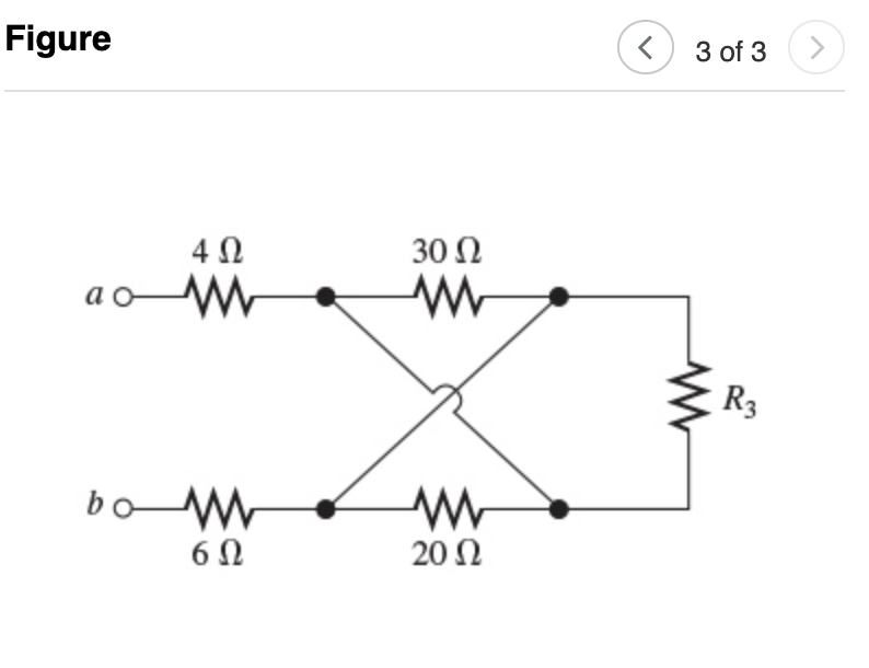
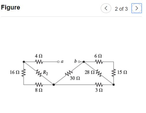
Solved Consider The Networks Shown In Figure 1 Figure Vrogue Co Consider the network shown in figure 1. with the indicated link costs, use dijkstra's shortest path algorithm to compute the shortest path from 𝑢 to all network nodes. show how the algorithm works using a table as follows:. Consider the building block called ‘network n’ shown in the figure. let c = 100 μf and r = 10 kΩ. two such blocks are connected in cascade, as shown in the figure: the transfer function v 3 (s) v 1 (s) of the cascaded network is. Consider the networks shown in (figure 1), (figure 2), and (figure 3). find the equivalent resistance between terminals a and b for the network show in (figure 1). supposse that r1=30Ω. express your answer to three significant figures and include the appropriate units. The „primary referred‟ values of the load elements are (1 n) 2 (16) and (1 n) 2 (1 j377c).

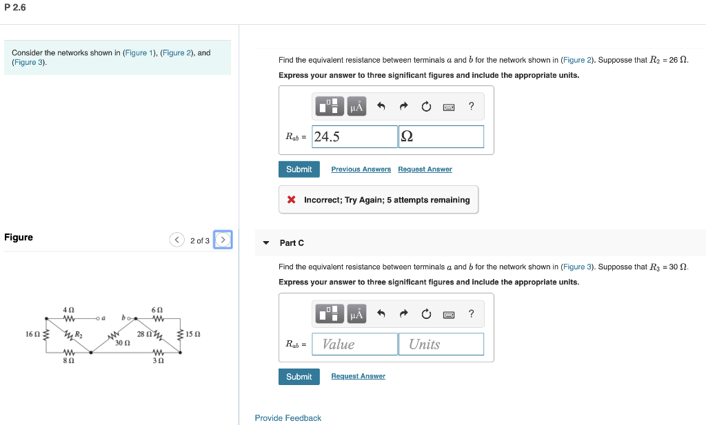
Solved Consider The Networks Shown In Figure 1 Figure Chegg Consider the networks shown in (figure 1), (figure 2), and (figure 3). find the equivalent resistance between terminals a and b for the network show in (figure 1). supposse that r1=30Ω. express your answer to three significant figures and include the appropriate units. The „primary referred‟ values of the load elements are (1 n) 2 (16) and (1 n) 2 (1 j377c). Find the equivalent resistance looking into terminals $a$ and $b$ in the figure. express your answer to three significant figures and include the appropriate units. Superposition example 1: consider the network shown in figure. calculate ia b and vc g using superposition theorem. Question: consider the networks shown in (figure 1). (figure 2), and (figure 3). part a find the equivalent resistance between terminals a and b for the network shown in (figure 1). supposse that r1 = 12 2. express your answer to three significant figures and include the appropriate units. ni μΑ ?. There are 2 steps to solve this one. here, in this question, only figure 1 is given. so, let's solve the question related to the shown fig p 2.6 consider the networks shown in (figure 1). (figure 2). and (figure 3) figure 1 of 3 4 0 60 300 60 15 2 find the equivalent resistance between terminals a and b for the network shown in (figure 1).

Solved Consider The Networks Shown In Figure 1 Figure Chegg Find the equivalent resistance looking into terminals $a$ and $b$ in the figure. express your answer to three significant figures and include the appropriate units. Superposition example 1: consider the network shown in figure. calculate ia b and vc g using superposition theorem. Question: consider the networks shown in (figure 1). (figure 2), and (figure 3). part a find the equivalent resistance between terminals a and b for the network shown in (figure 1). supposse that r1 = 12 2. express your answer to three significant figures and include the appropriate units. ni μΑ ?. There are 2 steps to solve this one. here, in this question, only figure 1 is given. so, let's solve the question related to the shown fig p 2.6 consider the networks shown in (figure 1). (figure 2). and (figure 3) figure 1 of 3 4 0 60 300 60 15 2 find the equivalent resistance between terminals a and b for the network shown in (figure 1).

Solved Consider The Networks Shown In Figure 1 Figure Chegg Question: consider the networks shown in (figure 1). (figure 2), and (figure 3). part a find the equivalent resistance between terminals a and b for the network shown in (figure 1). supposse that r1 = 12 2. express your answer to three significant figures and include the appropriate units. ni μΑ ?. There are 2 steps to solve this one. here, in this question, only figure 1 is given. so, let's solve the question related to the shown fig p 2.6 consider the networks shown in (figure 1). (figure 2). and (figure 3) figure 1 of 3 4 0 60 300 60 15 2 find the equivalent resistance between terminals a and b for the network shown in (figure 1).
