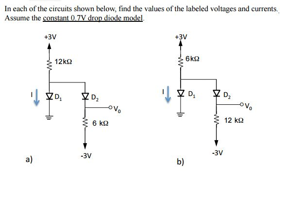
Solved In Each Of The Circuits Shown Below Find The Values Chegg Our expert help has broken down your problem into an easy to learn solution you can count on. question: for each of the circuits shown below, find the values of the voltage (v) and current (i) indicated. assume all diodes to be ideal. (a) (b) (u) there are 2 steps to solve this one. (a) the diode is in on condition. Consider the circuit below with the mesh currents. but, we need one more equation, so we use the constraint equation –i3 i4 = 10. this now gives us three equations with three unknows. we can.

Solved Based On The Following Circuits Find Values Read At Chegg In each of the circuits shown below, vin is a 1 khz sinusoid with amplitude 10 v. for each circuit, sketch the output waveform and state the values of the maximum and minimum output voltages. for this problem, use the ideal switch model of the diode. Circuit (a) is a parallel circuit: there are only two nodes and all four components are connected between them. circuit (b) is a series circuit: each node is connected to exactly two components and the same current. For each of the circuits shown below, find the values of the voltage (v) and current (i) indicated. assume all diodes to be ideal. a) b) i know that for (a) v= 3v, i=.6ma and (b) is v=3v, i=0.6ma. Apply kvl to each mesh containing an unknown mesh current, expressing each voltage in terms of one or more mesh currents solve the linear system of n–m unknowns. problem 3.1 solution: known quantities: circuit shown in figure p2.1 with mesh currents: i1 = 5 a, i2 = 3 a, i3 = 7 a. find: the branch currents through: a) r1, b) r2, c) r3.

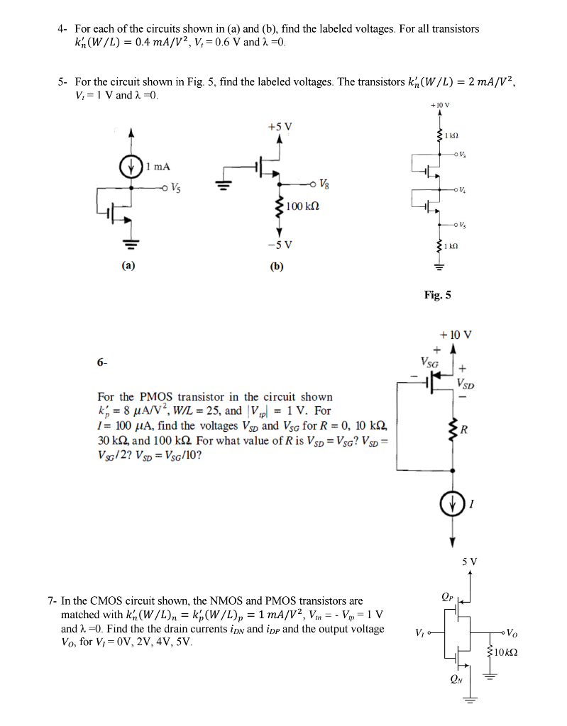
Solved For Each Of The Circuits Shown In Fig 1 Find Chegg For each of the circuits shown below, find the values of the voltage (v) and current (i) indicated. assume all diodes to be ideal. a) b) i know that for (a) v= 3v, i=.6ma and (b) is v=3v, i=0.6ma. Apply kvl to each mesh containing an unknown mesh current, expressing each voltage in terms of one or more mesh currents solve the linear system of n–m unknowns. problem 3.1 solution: known quantities: circuit shown in figure p2.1 with mesh currents: i1 = 5 a, i2 = 3 a, i3 = 7 a. find: the branch currents through: a) r1, b) r2, c) r3. Compute currents in simple circuits using kvl and ohm's law. use loop analysis method to compute loop currents. derive voltage division formula and analyze the limitations of of voltage divider. in practice we can encounter circuits that may have several electrical elements. For each case, identify the mode of operation of the transistor. 2. for each of the circuits shown in the circuit below, find the emitter, base, and collector voltages and. For each of the circuits shown in fig p4.44, find the labeled node voltages. the nmos transistors have vt = 1 v, and w k′. n l = 2 ma v2. assume λ = 0. for figure p4.44a we have vds1 = 2v − v1, and vgs1 = v − v1, where v = 5 v. thus, transistor 1 is operating in saturation. also notice that v2 = idr v . Chapter 7, problem 1. in the circuit shown in fig. 7.81 v(t) 56e 200tv, t > 0 ( 200tma, t > 0 it (a) find the values of r and c. (b) calculate the time constant t . (c) determine the time required for the voltage to decay half its initial value at figure 7.81 for prob. 7.1 chapter 7, solution 1. 8re 56 (a) t=rc 1 200 .

Solved For Each Of The Circuits Shown In A And B Find Chegg Compute currents in simple circuits using kvl and ohm's law. use loop analysis method to compute loop currents. derive voltage division formula and analyze the limitations of of voltage divider. in practice we can encounter circuits that may have several electrical elements. For each case, identify the mode of operation of the transistor. 2. for each of the circuits shown in the circuit below, find the emitter, base, and collector voltages and. For each of the circuits shown in fig p4.44, find the labeled node voltages. the nmos transistors have vt = 1 v, and w k′. n l = 2 ma v2. assume λ = 0. for figure p4.44a we have vds1 = 2v − v1, and vgs1 = v − v1, where v = 5 v. thus, transistor 1 is operating in saturation. also notice that v2 = idr v . Chapter 7, problem 1. in the circuit shown in fig. 7.81 v(t) 56e 200tv, t > 0 ( 200tma, t > 0 it (a) find the values of r and c. (b) calculate the time constant t . (c) determine the time required for the voltage to decay half its initial value at figure 7.81 for prob. 7.1 chapter 7, solution 1. 8re 56 (a) t=rc 1 200 .

Solved For The Circuit Shown Fig 2b Find The Values Of The Chegg For each of the circuits shown in fig p4.44, find the labeled node voltages. the nmos transistors have vt = 1 v, and w k′. n l = 2 ma v2. assume λ = 0. for figure p4.44a we have vds1 = 2v − v1, and vgs1 = v − v1, where v = 5 v. thus, transistor 1 is operating in saturation. also notice that v2 = idr v . Chapter 7, problem 1. in the circuit shown in fig. 7.81 v(t) 56e 200tv, t > 0 ( 200tma, t > 0 it (a) find the values of r and c. (b) calculate the time constant t . (c) determine the time required for the voltage to decay half its initial value at figure 7.81 for prob. 7.1 chapter 7, solution 1. 8re 56 (a) t=rc 1 200 .
