Solved Consider The Circuit Shown In Figure 1 Suppose Chegg For the circuit shown in figure 1, determine whether or not the diode is conducting. assume an ideal diode. remember to show how you arrived at your answer. your solution’s ready to go! our expert help has broken down your problem into an easy to learn solution you can count on. A) determine vgs and drain current id and vds for the mosfet circuit in figure below. assume threshold voltage vth = 1 v and conduction parameter k = 0.1 ma v2 b) if vds (sat) = vgs vth, determine whether the transistor is biased in saturation mode or not.

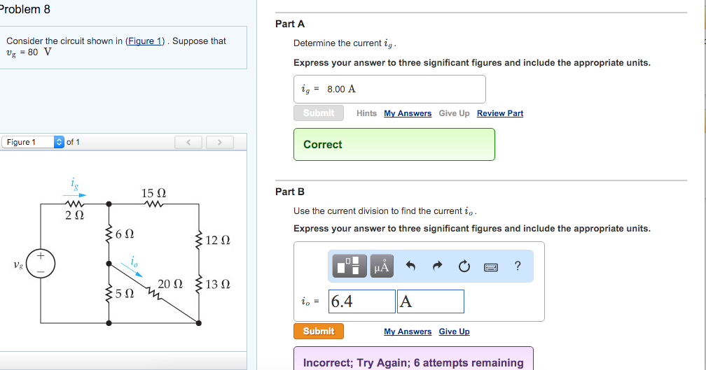
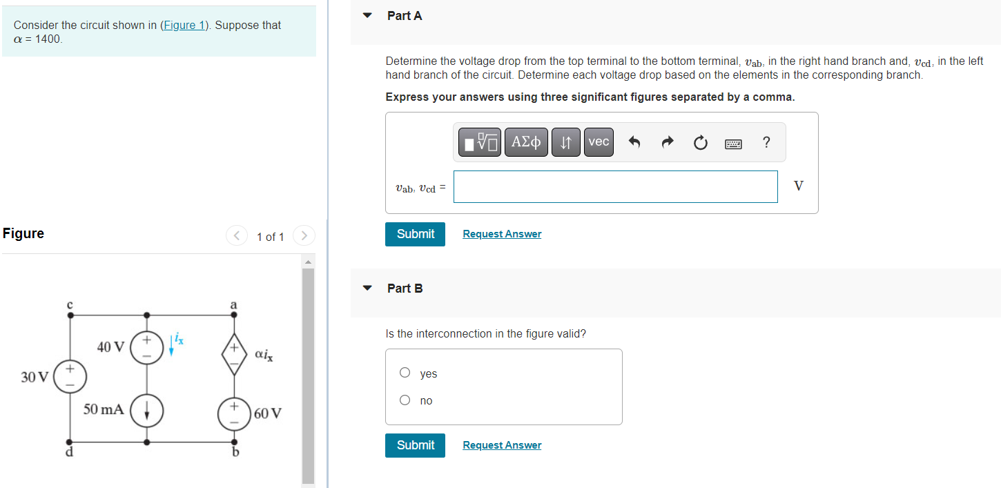
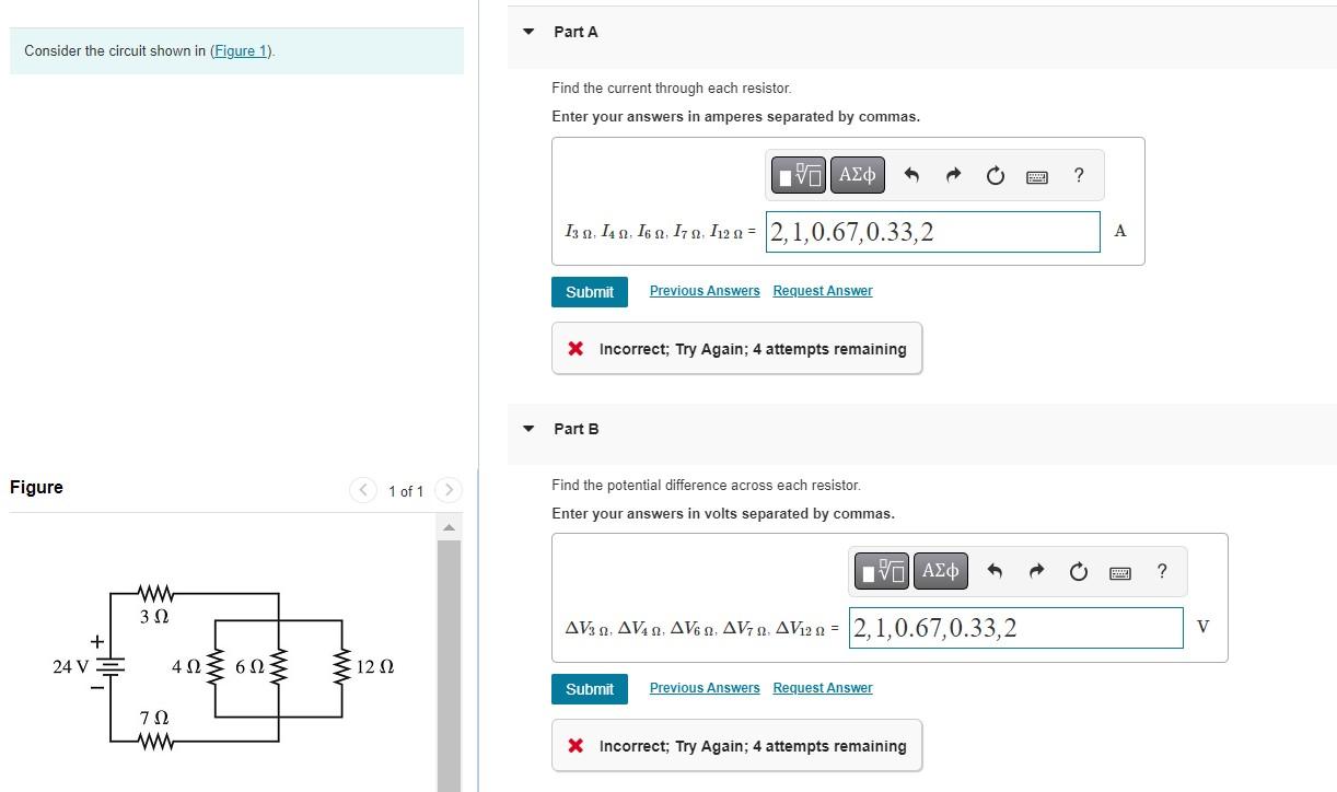
Solved 1 Consider The Circuit Shown In Figure 1 Below Chegg Q1. for the circuit shown in fig.1 (i), find : (i) the output voltage (ii) the voltage drop across series resistance (iii) the current through zener diode. fig.1 (i) solution : if you remove the zener diode in fig. 1, the voltage v across the open circuit is given by :. Determine the equivalent resistance of the circuit shown in the figure. (figure 1) determine the voltage across 820 Ω resistor. determine the voltage across 960 Ω resistor. determine the voltage across 680 Ω resistor. We will explain the steps required to obtain the solution by considering the circuit example shown on figure 1. figure 1. a typical resistive circuit. the node method. a voltage is always defined as the potential difference between two points. For the circuit shown in figure 1, (i) determine the total impedance zr in rectangular and in polar forms. (ii) draw the impedance diagram (iii) find the current i, and the voltages vr,vl and vc in phasor form (iv) find the average power delivered to the circuit (v) find the power factor and indicate whether it is.

Solved Consider The Circuit Shown In Figure 1 Suppose Chegg We will explain the steps required to obtain the solution by considering the circuit example shown on figure 1. figure 1. a typical resistive circuit. the node method. a voltage is always defined as the potential difference between two points. For the circuit shown in figure 1, (i) determine the total impedance zr in rectangular and in polar forms. (ii) draw the impedance diagram (iii) find the current i, and the voltages vr,vl and vc in phasor form (iv) find the average power delivered to the circuit (v) find the power factor and indicate whether it is. Determine the current through the capacitor. the current through the capacitor is 13.060 ± sin(377t) a. explanation: 60 x 10 = 333333.3 cos2(377t) v(t) = ±577.4 cos(377t) v assume that v(t) = 577.4 cos(377t) v. . (t) = 60 x 10 6 f x 577.4 x ( 377 sin(377t)) v 13.060 sin(377t) a the current through the capacitor is 13.060 sin(377t) a. . 1) calculate the equivalent resistance of the circuit. first combine all the series resistors and then calculate the parallel ones. use the following equations: series: req = ∑in ri (5.6.1) (5.6.1) series: r e q = ∑ i n r i. parallel: 1 req = ∑in 1 ri (5.6.2) (5.6.2) parallel: 1 r e q = ∑ i n 1 r i. Problem sheet 1 (lectures 1 & 2) key: [a]= easy [e]=hard a series circuit and t [b] find the power absorbed by by each of the subcircuits a and b given that the voltage and current are 10 v and 2 a as shown. [b] for each of the four circuits below, nd the power absorbed. Loop analysis is a systematic procedure based on kvl to solve for currents in more complex circuits. loop current analysis involves the following steps: identify loops in a circuit. pick currents in clockwise direction. set up loop equations. solve system of equations to obtain unknown currents.

Solved Consider The Circuit Shown In The Figure Chegg Vrogue Co Determine the current through the capacitor. the current through the capacitor is 13.060 ± sin(377t) a. explanation: 60 x 10 = 333333.3 cos2(377t) v(t) = ±577.4 cos(377t) v assume that v(t) = 577.4 cos(377t) v. . (t) = 60 x 10 6 f x 577.4 x ( 377 sin(377t)) v 13.060 sin(377t) a the current through the capacitor is 13.060 sin(377t) a. . 1) calculate the equivalent resistance of the circuit. first combine all the series resistors and then calculate the parallel ones. use the following equations: series: req = ∑in ri (5.6.1) (5.6.1) series: r e q = ∑ i n r i. parallel: 1 req = ∑in 1 ri (5.6.2) (5.6.2) parallel: 1 r e q = ∑ i n 1 r i. Problem sheet 1 (lectures 1 & 2) key: [a]= easy [e]=hard a series circuit and t [b] find the power absorbed by by each of the subcircuits a and b given that the voltage and current are 10 v and 2 a as shown. [b] for each of the four circuits below, nd the power absorbed. Loop analysis is a systematic procedure based on kvl to solve for currents in more complex circuits. loop current analysis involves the following steps: identify loops in a circuit. pick currents in clockwise direction. set up loop equations. solve system of equations to obtain unknown currents.

Solved Consider The Circuit Shown In Figure 1 Chegg Problem sheet 1 (lectures 1 & 2) key: [a]= easy [e]=hard a series circuit and t [b] find the power absorbed by by each of the subcircuits a and b given that the voltage and current are 10 v and 2 a as shown. [b] for each of the four circuits below, nd the power absorbed. Loop analysis is a systematic procedure based on kvl to solve for currents in more complex circuits. loop current analysis involves the following steps: identify loops in a circuit. pick currents in clockwise direction. set up loop equations. solve system of equations to obtain unknown currents.
