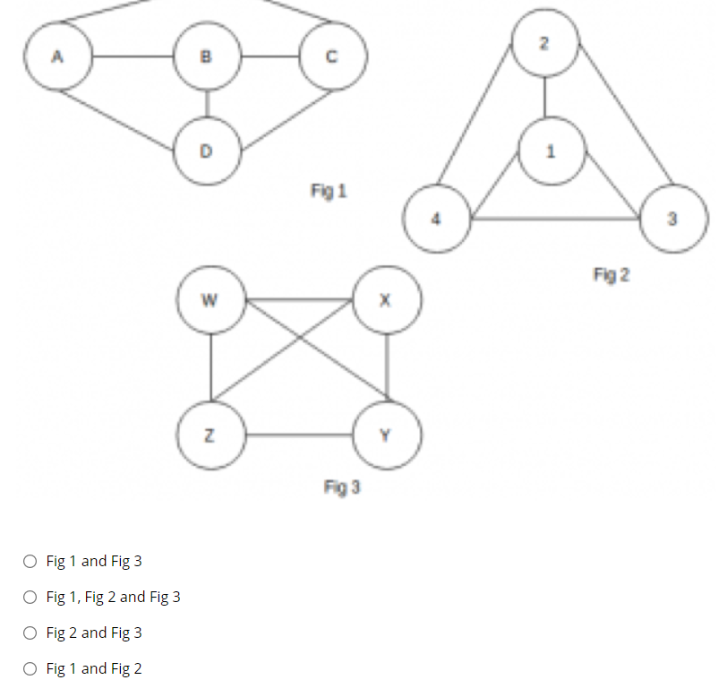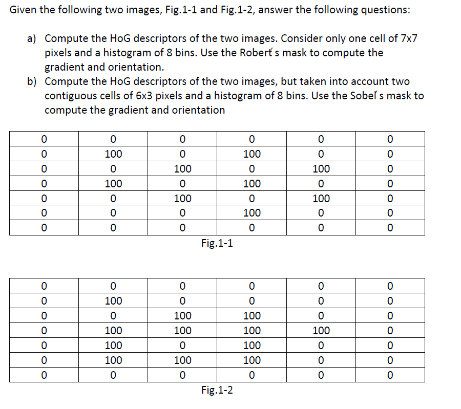
Solved Fig 1 3 Fig 2 N Fig 1 And Fig 3 O Fig 1 Fig 2 And Chegg Given the following two images, fig.1 1 and fig.1 2, answer the following questions: a) compute the hog descriptors of the two images. consider only one cell of 7 × 7 pixels and a histogram of 8 bins. use the robert's mask to compute the gradient and orientation. Problem 1: consider the two image subsets, s1 and s2, shown in the following figure. for v={1}, determine whether these two subsets are (a) 4 adjacent, (b) 8 adjacent, or (c) m adjacent. problem 2: consider the image segment shown. ⋆ (a) let v={0,1} and compute the lengths of the shortest 4 , 8 , and m path between p and q.

Solved Given The Following Two Images Fig 1 1 And Fig 1 2 Chegg Solution to create a digital image, continuous sensed data needs to be converted into digital form, which involves two processes : sampling and quantization. sampling is the process in which the coordinate values of an image are digitized. quantization is the process in which the amplitude values of an image are digitized. 4. A 2x2 image is given in fig.4. interpolate this by a factor of 2 and fill in the missing values by convolving upsampled image with spatial domain low pass filter given in fig 5 . 1) for an image given by the function f(x,y) = (x y)3 where x,y are continuous variables; evaluate f(x,y)δ(x−1,y−2) and f(x,y)∗δ(x−1,y−2), where δ is the dirac delta function. 2) for the optical imaging system shown below, consisting of an image scaling and two forward. Histogram of a 3 bit image is shown in the following table. find optimal threshold using otsu. solution. plotting histogram. between class variance σ2b. σ2b =c1(1 −c1)(μ1 −μ2)2. it is clear that optimal threshold is 3. σ2b at t = 3. c1 = 2 3 2 1 16 = 1 2. μ1 = 0 × 2 1 × 3 2 × 2 3 × 1 2 3 2 1 = 10 8.

Solved Fig 1 1 Fig 1 2 Chegg 1) for an image given by the function f(x,y) = (x y)3 where x,y are continuous variables; evaluate f(x,y)δ(x−1,y−2) and f(x,y)∗δ(x−1,y−2), where δ is the dirac delta function. 2) for the optical imaging system shown below, consisting of an image scaling and two forward. Histogram of a 3 bit image is shown in the following table. find optimal threshold using otsu. solution. plotting histogram. between class variance σ2b. σ2b =c1(1 −c1)(μ1 −μ2)2. it is clear that optimal threshold is 3. σ2b at t = 3. c1 = 2 3 2 1 16 = 1 2. μ1 = 0 × 2 1 × 3 2 × 2 3 × 1 2 3 2 1 = 10 8. Consider the two images subsets, s1 and s2, shown in the following figure. for v={1}, determine whether these two subsets are (a) 4 adjacent, (b) 8 adjacent, or. (c) m adjacent. 2. consider the image segment shown. (a) let v = {0, 1} and compute the lengths of the shortest 4 , 8 , and m path between p and q. The transfer function of the open loop system is given by: c r = g. the transfer function of the closed loop system is given by: c r = g 1 g h. where, c = output. r = input. g = forward path gain. h = feedback path gain. calculation: figure 1 is an open loop system whereas figure 2 is a closed loop system. in figure 1:. 2 d signals: a continuous image is represented by a function of two variables e.g. x(u;v) where (u;v) are called spatial coordinates and xis the intensity. a sampled image is represented by x(m;n). if pixel intensity is also quantized (digital images) then each pixel is represented by b bits (typically b= 8 bits pixel). Nodes 1 and 2 form a supernode; so do nodes 1 and 3. hence between nodes 1 and 3, similarly, between nodes 1 and 2, but i = v 3 4. combining this with (2) and (3) gives solving.

Solved Fig 2 Chegg Consider the two images subsets, s1 and s2, shown in the following figure. for v={1}, determine whether these two subsets are (a) 4 adjacent, (b) 8 adjacent, or. (c) m adjacent. 2. consider the image segment shown. (a) let v = {0, 1} and compute the lengths of the shortest 4 , 8 , and m path between p and q. The transfer function of the open loop system is given by: c r = g. the transfer function of the closed loop system is given by: c r = g 1 g h. where, c = output. r = input. g = forward path gain. h = feedback path gain. calculation: figure 1 is an open loop system whereas figure 2 is a closed loop system. in figure 1:. 2 d signals: a continuous image is represented by a function of two variables e.g. x(u;v) where (u;v) are called spatial coordinates and xis the intensity. a sampled image is represented by x(m;n). if pixel intensity is also quantized (digital images) then each pixel is represented by b bits (typically b= 8 bits pixel). Nodes 1 and 2 form a supernode; so do nodes 1 and 3. hence between nodes 1 and 3, similarly, between nodes 1 and 2, but i = v 3 4. combining this with (2) and (3) gives solving.

Solved Fig 1 Chegg 2 d signals: a continuous image is represented by a function of two variables e.g. x(u;v) where (u;v) are called spatial coordinates and xis the intensity. a sampled image is represented by x(m;n). if pixel intensity is also quantized (digital images) then each pixel is represented by b bits (typically b= 8 bits pixel). Nodes 1 and 2 form a supernode; so do nodes 1 and 3. hence between nodes 1 and 3, similarly, between nodes 1 and 2, but i = v 3 4. combining this with (2) and (3) gives solving.
