Solved Part A Consider The Circuit Shown In Figure 1 Solve Chegg
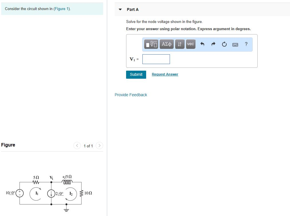
Solved Consider The Circuit Shown In Figure 1 Part A Solve Chegg Unlock the full potential of your logitech g gaming gear with g hub, the advanced gaming software that lets you customize and optimize your mouse, keyboard, headset, speaker, and webcam settings. download profiles from other gamers, create your own, and much more. Unlock full potential with g hub! customize logitech g gear: mouse, keyboard, headset, webcam settings. create and share profiles for optimal gaming.
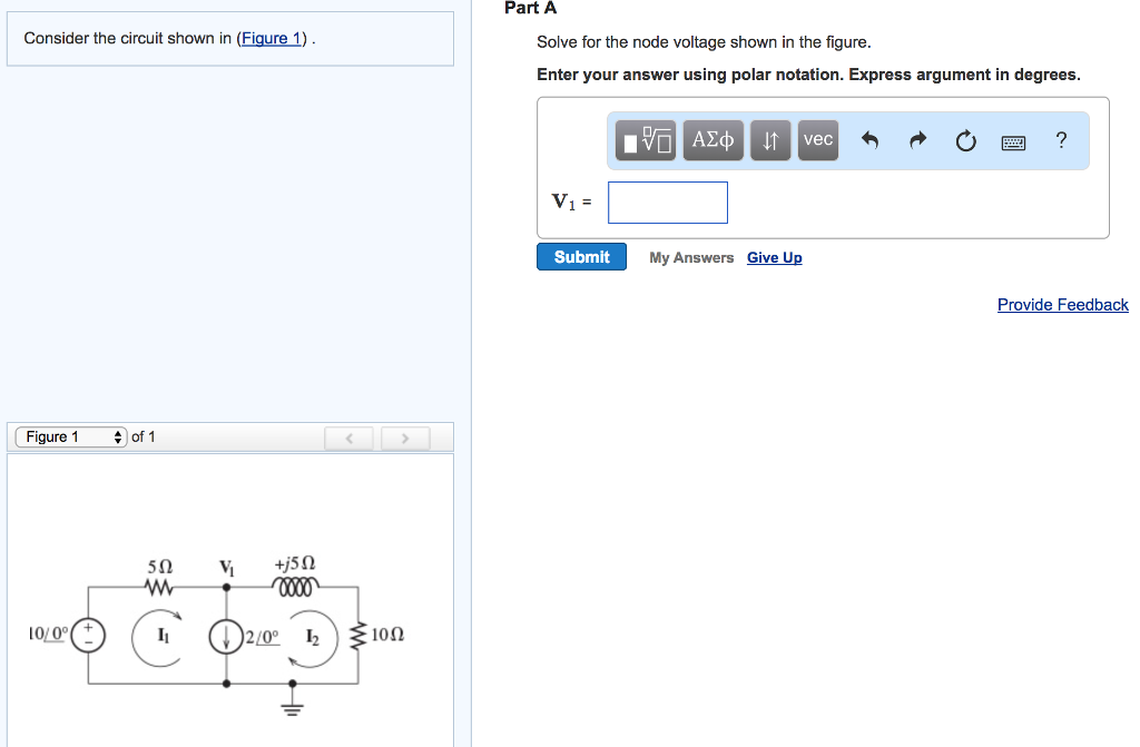
Solved Part A Consider The Circuit Shown In Figure 1 Solve Chegg Logitech g hub logitech g hub software lets you customize logitech g gaming mice, keyboards, headsets, speakers, and other devices. Logitech g hub, free download for windows. customize mouse, keyboards and headsets for a personalized gaming experience. Logitech is a leading gaming accessory manufacturer that makes customizable computer peripherals that you can configure according to your gaming requirements and styles. but to do this, you will need to install logitech g hub on your windows mac computer. Logitech g hub is a powerful application that brings customization and management of all your logitech g gear under one roof on windows 11. this guide will show you how to download, install, and utilize logitech g hub to enhance your gaming setup.
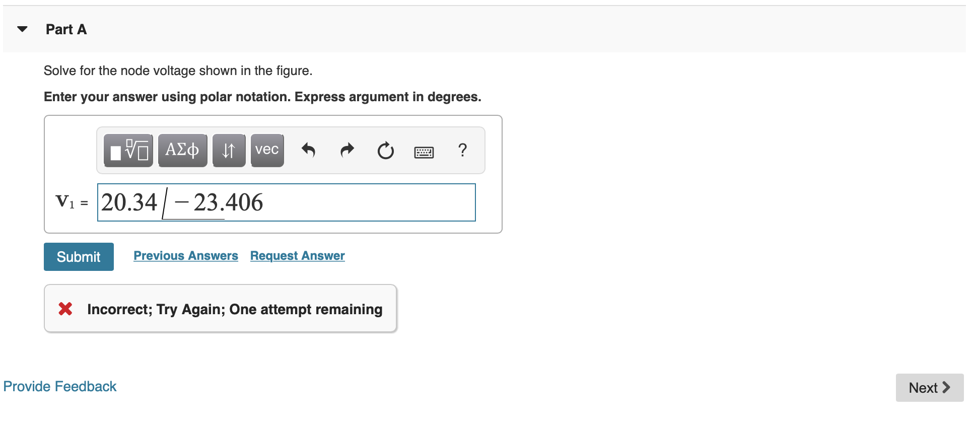
Solved Consider The Circuit Shown In Figure 1 Part A Solve Chegg Logitech is a leading gaming accessory manufacturer that makes customizable computer peripherals that you can configure according to your gaming requirements and styles. but to do this, you will need to install logitech g hub on your windows mac computer. Logitech g hub is a powerful application that brings customization and management of all your logitech g gear under one roof on windows 11. this guide will show you how to download, install, and utilize logitech g hub to enhance your gaming setup. Logitech g hub is an all in one periphery management solution that offers owners of logitech accessories (such as keyboards, mice, audio headsets, and more) a simple way to not only control their hardware capabilities but also manage their usage with a wide array of gaming software. Total gear control with g hub logitech g hub gives you a single portal for optimizing and customizing all your supported logitech g gear: mice, keyboards, headsets, speakers, and webcams. Learn the basics of logitech g hub software to get the most out of your g gear. customize settings, explore features, and optimize your gaming experience. We would like to show you a description here but the site won’t allow us.
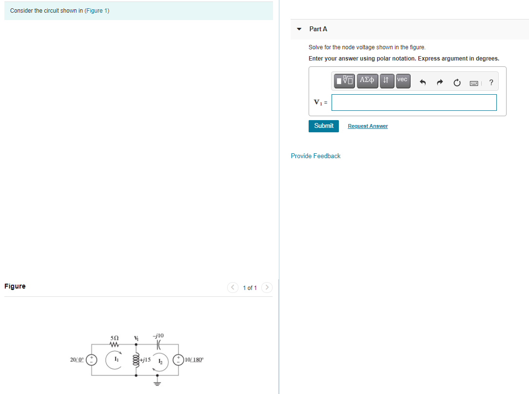
Solved Consider The Circuit Shown In Figure 1 Part A Solve Chegg Logitech g hub is an all in one periphery management solution that offers owners of logitech accessories (such as keyboards, mice, audio headsets, and more) a simple way to not only control their hardware capabilities but also manage their usage with a wide array of gaming software. Total gear control with g hub logitech g hub gives you a single portal for optimizing and customizing all your supported logitech g gear: mice, keyboards, headsets, speakers, and webcams. Learn the basics of logitech g hub software to get the most out of your g gear. customize settings, explore features, and optimize your gaming experience. We would like to show you a description here but the site won’t allow us.

Solved 1 Consider The Circuit Shown In Figure 1 Below Chegg Learn the basics of logitech g hub software to get the most out of your g gear. customize settings, explore features, and optimize your gaming experience. We would like to show you a description here but the site won’t allow us.
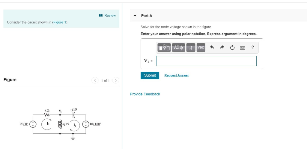
Solved Review Part A Consider The Circuit Shown In Figure Chegg
Comments are closed.