Solved Q1 Given The The Forces As Shown Determine The Sum Chegg Given the the forces as shown, determine the sum of the forces f ˉ 1 and f ˉ 2 for the following cases by following the procedure: 1. f ˉ 1 = f ˉ 1 x ^ f ˉ 1 y ^ 2. f ˉ 2 = f 2 x ^ f 2 y ^ 3. Given a system of forces as shown in figure q1. (a) express each force acting on the pipe assembly in cartesian vector form (cvn). (2 mark) (b) determine the magnitude and direction of the resultant force acting on the pipe assembly.

Solved In The Problems Given Below Determine The Forces In Chegg Solution: first, find the electric force due to each charge on the q3, then use the superposition principle to do the vector sum of them. in the figure below, all forces on q3 are sketched. recall that the like charges repel each other and unlike charges attract. Study with quizlet and memorize flashcards containing terms like the three scalar equations, ∑fx = ∑fy = ∑mo = 0, are equations of equilibrium in two dimensions., a rigid body is subjected to forces as shown. Determine the resultant of the three forces acting on the dam shown in fig. p 266 and locate its intersection with the base ab. for good design, this intersection should occur within the middle third of the base. Given a system of forces as shown in figure q1 (a) express each force acting on the pipe assembly in cartesian vector form (cvn). (2 mark) 6) determine the magnitude and direction of the resultant force acting on the pipe assembly (10 mark) (a) assume that fl is a spanner with coordinate (4.0.3).

Solved Q1 Determine The Resultant Forces In The Given Chegg Determine the resultant of the three forces acting on the dam shown in fig. p 266 and locate its intersection with the base ab. for good design, this intersection should occur within the middle third of the base. Given a system of forces as shown in figure q1 (a) express each force acting on the pipe assembly in cartesian vector form (cvn). (2 mark) 6) determine the magnitude and direction of the resultant force acting on the pipe assembly (10 mark) (a) assume that fl is a spanner with coordinate (4.0.3). Refer to figure 10.41. due to application of line loads q1 and q2, the vertical stress increase at point a is 42 kn m2. determine the magnitude of q2. step by step solution. step 1 of 6. show the line loads on the soil element as shown in the figure. comment. Q1: determine the resultant forces in the given systems. use both parallellogram theorem and force direction method. a) (a = 30 degrees, p = 100 n) b) q2: a welded connection is in under equilibrium under the action of four forces shown. The document provides solutions to multiple problems involving calculating support reactions for beams. the problems involve drawing free body diagrams of beams, then applying equations for the sum of forces and sum of moments at the supports to solve for the unknown support reactions. (a) find the magnitudes of the forces \vec {f 1} f 1 and \vec {f 2} f 2 that add to give the total force \vec {f {\textrm {tot}}} f tot shown in figure 4.35. this may be done either graphically or by using trigonometry.

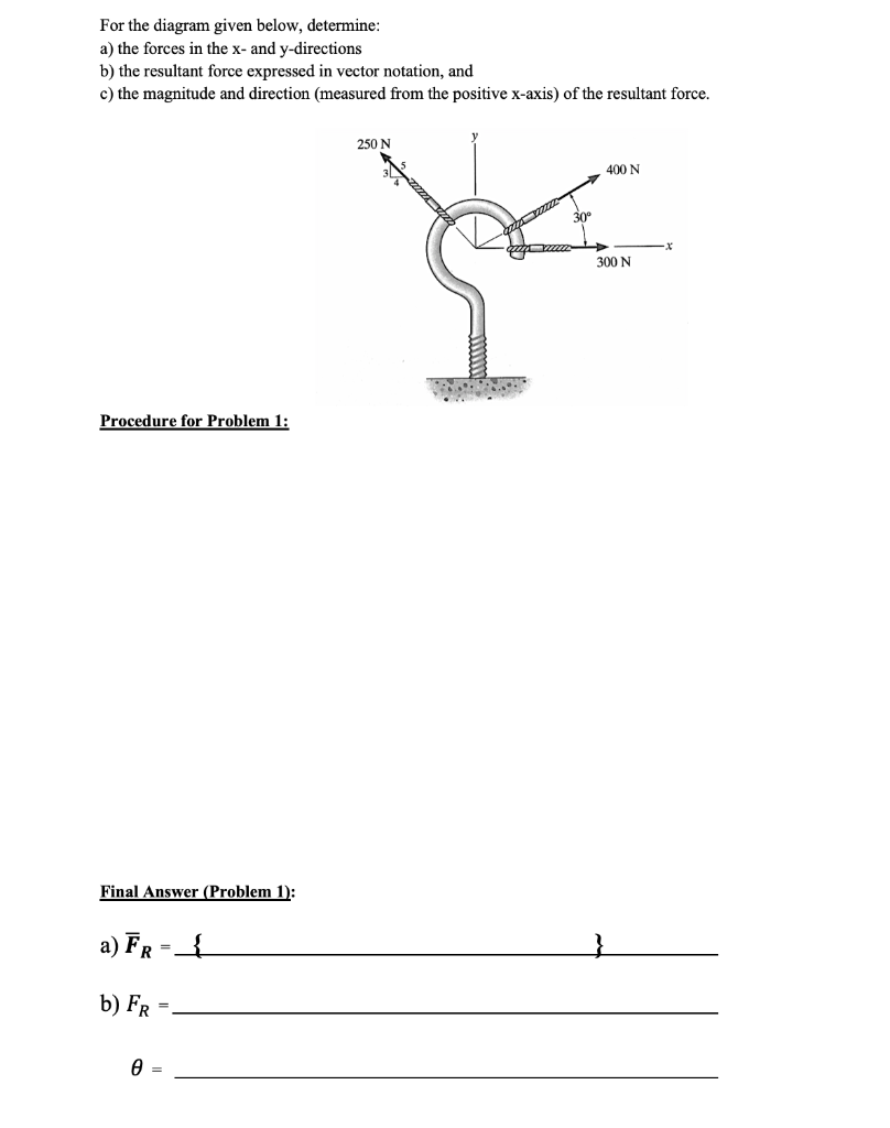
Solved For The Diagram Given Below Determine A The Forces Chegg Refer to figure 10.41. due to application of line loads q1 and q2, the vertical stress increase at point a is 42 kn m2. determine the magnitude of q2. step by step solution. step 1 of 6. show the line loads on the soil element as shown in the figure. comment. Q1: determine the resultant forces in the given systems. use both parallellogram theorem and force direction method. a) (a = 30 degrees, p = 100 n) b) q2: a welded connection is in under equilibrium under the action of four forces shown. The document provides solutions to multiple problems involving calculating support reactions for beams. the problems involve drawing free body diagrams of beams, then applying equations for the sum of forces and sum of moments at the supports to solve for the unknown support reactions. (a) find the magnitudes of the forces \vec {f 1} f 1 and \vec {f 2} f 2 that add to give the total force \vec {f {\textrm {tot}}} f tot shown in figure 4.35. this may be done either graphically or by using trigonometry.
