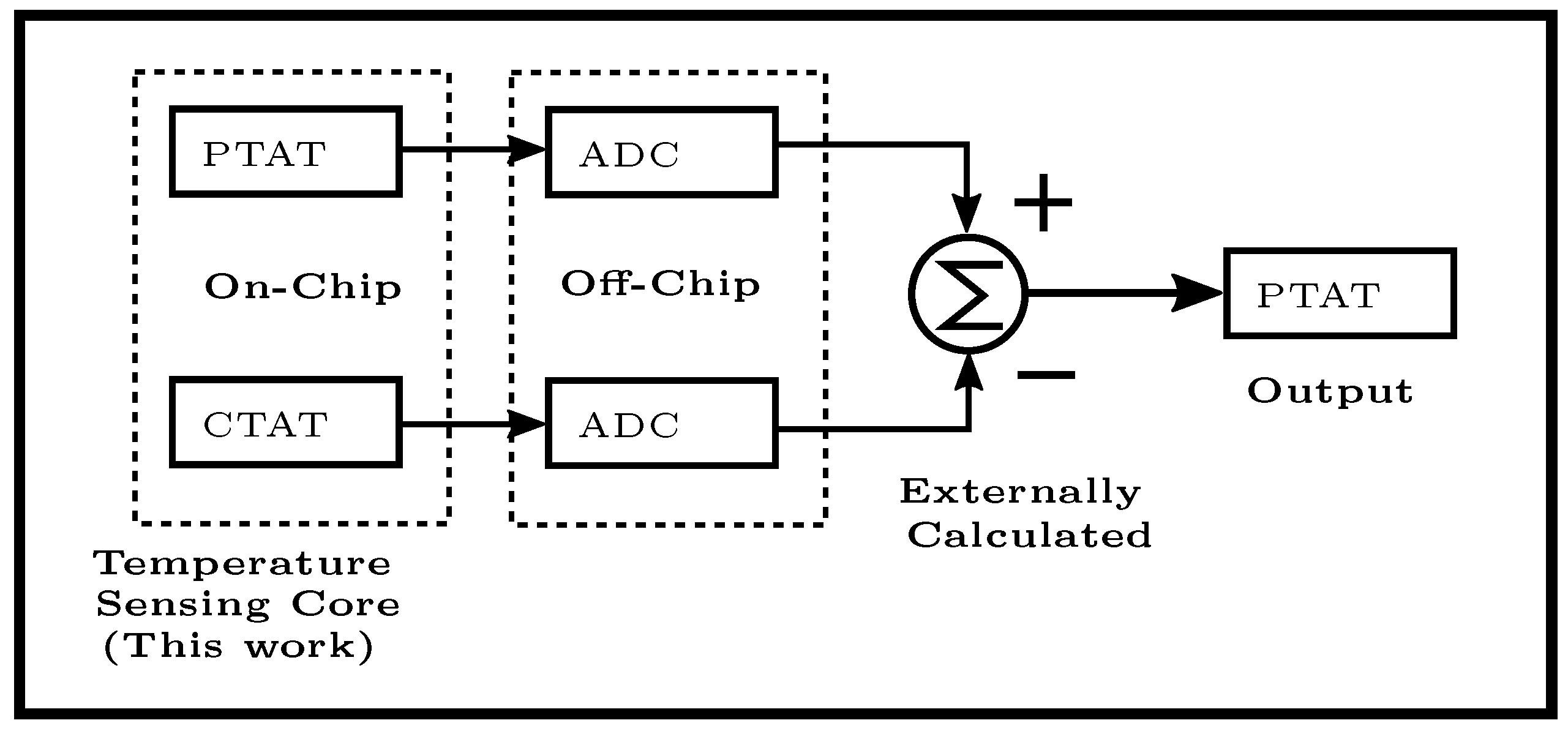
Temperature Sensor Circuit Diagram Super Circuit Diagram

Temperature Sensor Circuit Circuit Diagram This circuit is intended to control a heating system or central heating plan, keeping constant indoor temperature in spite of wide range changes in the outdoor one. By following this diagram, engineers can construct a temperature sensing circuit that works to detect, measure, and monitor temperature levels in a given environment.
Circuit Diagram Temperature Sensor Circuit Diagram This temperature sensing circuit uses a resistor in series with a negative–temperature–coefficient (ntc) thermistor to form a voltage divider, which has the effect of producing an output voltage that is linear over temperature. Practical circuits and interface techniques will be provided for embedded applications with thermocouples, resistive temperature detectors (rtds), thermistors and silicon integrated circuit temperature sensors. The concepts used in the bandgap temperature sensor discussion above can be used as the basis for a variety of ic temperature sensors to generate either current or voltage outputs. This article will delve into the basics of temperature sensor circuits, explore different types of sensors, and provide a detailed example of a circuit diagram.

Schematic Diagram Temperature Sensor Circuit Diagram The concepts used in the bandgap temperature sensor discussion above can be used as the basis for a variety of ic temperature sensors to generate either current or voltage outputs. This article will delve into the basics of temperature sensor circuits, explore different types of sensors, and provide a detailed example of a circuit diagram. The schematic shown here is a project of a simple temperature sensor circuit or we can also say it a heat sensor circuit, which will activate an led when receive heat. Learn how to build a digital temperature controller circuit with a detailed circuit diagram and step by step instructions. control temperature with precision and accuracy. It includes all of the parts, wiring diagrams, code, and step by step instructions for 58 different robotics and internet of things projects that are super fun to build!. In the circuit described here, the sensor (ic2) generates an output voltage of 10 mv °c, so the minimum temperature that can be measured is 0 °c. at 25 °c, the output voltage of the sensor is (25 °c × 10 mv °c) = 0.25 v. the circuit uses a tlc271 opamp as a comparator.

Electronic Temperature Sensor Circuit Diagram Circuit Diagram The schematic shown here is a project of a simple temperature sensor circuit or we can also say it a heat sensor circuit, which will activate an led when receive heat. Learn how to build a digital temperature controller circuit with a detailed circuit diagram and step by step instructions. control temperature with precision and accuracy. It includes all of the parts, wiring diagrams, code, and step by step instructions for 58 different robotics and internet of things projects that are super fun to build!. In the circuit described here, the sensor (ic2) generates an output voltage of 10 mv °c, so the minimum temperature that can be measured is 0 °c. at 25 °c, the output voltage of the sensor is (25 °c × 10 mv °c) = 0.25 v. the circuit uses a tlc271 opamp as a comparator.

Temperature Sensor Schematic Diagram Circuit Diagram It includes all of the parts, wiring diagrams, code, and step by step instructions for 58 different robotics and internet of things projects that are super fun to build!. In the circuit described here, the sensor (ic2) generates an output voltage of 10 mv °c, so the minimum temperature that can be measured is 0 °c. at 25 °c, the output voltage of the sensor is (25 °c × 10 mv °c) = 0.25 v. the circuit uses a tlc271 opamp as a comparator.

Temperature Sensor Circuit Diagram Super Circuit Diagram
Comments are closed.