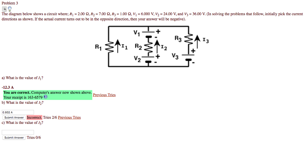
Solved Problem 3 The Diagram Below Shows A Circuit Where Ri Chegg The diagram below shows a circuit where ri = 3.0 Ω, rz = 6.0 Ω, rz = 4.0 Ω, v = 20.2 volts, vz = 7.2 volts, and vz = 1.5 volts. what is the value of 11? i. First, we can write the kirchhoff's loop equations for the three loops in the circuit: loop 1 (r1 and v1): $v 1 i 1 r 1 = 0$ loop 2 (r2 and v2): $v 2 i 2 r 2 = 0$ loop 3 (r3 and v3): $v 3 i 3 r 3 = 0$ now, we can write the kirchhoff's junction equation for the junction where all three resistors meet: $i 1 i 2 i 3 = 0$ we are given the.

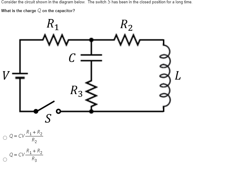
Solved Consider The Circuit Shown In The Diagram Below The Switch Has Been In The Closed The diagram below shows a 6.0 v battery connected to three resistors. how much current is the circuit drawing from the battery?watch the full video at:https:. Question: three resistors three batteries the diagram below shows a circuit where; r = 6.0 a, r2 = 3.0, r = 7,0 v 1.1 volts, v = 12.0 volts, and vj = 9.0 volts. what is the value of hi? in solving this problem, initially pick the current directions as shown. Study with quizlet and memorize flashcards containing terms like a 20 ohm resistor and a 30 ohm resistor are connected in parallel to a 12 volt battery. what is the power of the 30 ohm resistor?, diagram below represents part of an electric circuit with three resistors. Use the concept of equivalent circuit to determine voltage, current, and power for non linear loads by using load line analysis and analytical methods. section 3. problem 3. use node voltage analysis to find the voltages v 1 and v 2 for the circuit of figure p3. known quantities: circuit shown in figure p3. 1 find: voltages v 1 and v 2.

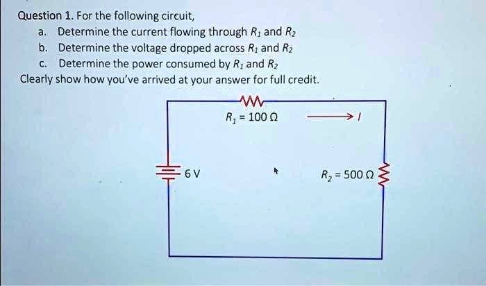
Solved Question 1 For The Following Circuit Determine The Current Flowing Through Ri And Rz Study with quizlet and memorize flashcards containing terms like a 20 ohm resistor and a 30 ohm resistor are connected in parallel to a 12 volt battery. what is the power of the 30 ohm resistor?, diagram below represents part of an electric circuit with three resistors. Use the concept of equivalent circuit to determine voltage, current, and power for non linear loads by using load line analysis and analytical methods. section 3. problem 3. use node voltage analysis to find the voltages v 1 and v 2 for the circuit of figure p3. known quantities: circuit shown in figure p3. 1 find: voltages v 1 and v 2. The circuit shown below shows a thermistor connected in a circuit with two resistors, an ammeter and a battery of emf 15v and negligible internal resistance. (a) when the thermistor is at a certain temperature the current through the ammeter is 10.0ma. 3) analyze the circuit below using a v i r chart: values ri 6.0 q2 rz = 6.0 q r; = 2.40 ry = 6.0 q …. In this circuit, ri and rz are connected in parallel. therefore, we can calculate their equivalent resistance as follows: 1 rp = 1 ri 1 rz 1 rp = 1 3.0 1 6.0 1 rp = 0.5 rp = 2.0 Ωanswerstep 4: simplify the series resistors. to simplify the series resistors, we can add their values together. Consider the circuit shown. match the resistor (s) to the voltage drop across them. r2 3 volt, r4 9 volt, r2 r3 r4 12 volts, and r1 6 volt. in complex circuits, you may be required to apply both of kirchhoff's laws. two 2 ohms resistors in parallel are equivalent to a 1 ohm resistor.
